Is there any oscillation on the audio output transistors?
Is there any DC across the speaker terminals of any channel?
Are the gate resistors for the output FETs within tolerance?
With no power applied and no signal cables connected, what's the resistance from the RCA shields to the center tap of the power transformer's secondary windings?
Is there any DC across the speaker terminals of any channel?
Are the gate resistors for the output FETs within tolerance?
With no power applied and no signal cables connected, what's the resistance from the RCA shields to the center tap of the power transformer's secondary windings?
DC outputs on the speaker terminals.
Ch1 110mv
Ch2 130mv
Ch3 200mv
Ch4 85mv
Ch5 0.1mv
350 ohms on both right input grounds
210 ohms on both left input grounds
Could the gate resistor be a tiny SMT device? Measuring it on the PCB they all read 222ohms, but they are stamped 68.1kohm
There is alot of noise on the pins of the fets:
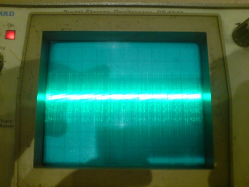
And if I 'zoom' to 10mv/div and narrow the time to 10us/div there is some oscillation:
Ch1 110mv
Ch2 130mv
Ch3 200mv
Ch4 85mv
Ch5 0.1mv
350 ohms on both right input grounds
210 ohms on both left input grounds
Could the gate resistor be a tiny SMT device? Measuring it on the PCB they all read 222ohms, but they are stamped 68.1kohm
There is alot of noise on the pins of the fets:
And if I 'zoom' to 10mv/div and narrow the time to 10us/div there is some oscillation:
The gate resistor could be an SMD resistor. It's not likely to be 68k though. That's too high. It's more likely to be closer to the 200 ohms that you measured.
The noise could be due to a poor ground point. Ground your scope probe to the secondary center tap (NOT the primary center tap). The secondary center tap is very near zero volts (referenced to the ground terminal of the amp). The primary center tap has 12v on it.
Disconnect everything from the amp and measure the resistance from the primary center tap to the secondary center tap.
Yep, your right about the gate resistor.... I got out the magnifying glass and its stamped 2210. I don't know where I got 6812 from!
Anyway they all measure approx 222 ohms.
The primary to secondary centre taps measure infinate resistance.
The scope was connected with its ground on the centre tap of the secondary.
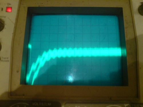
The rectified power rails even have a load of noise on them.
Could this still be a problem in the power supply section? I'm only getting about +/- 1V at secondary rails. Or does this indicate a short in the amp and the SMPS just isnt starting properly?
Anyway they all measure approx 222 ohms.
The primary to secondary centre taps measure infinate resistance.
The scope was connected with its ground on the centre tap of the secondary.
The rectified power rails even have a load of noise on them.
Could this still be a problem in the power supply section? I'm only getting about +/- 1V at secondary rails. Or does this indicate a short in the amp and the SMPS just isnt starting properly?
It appears that excessive current draw from the audio section is either causing the amp to go into protection or it's simply not allowing the secondary voltage to rise.
Are you 100% sure you have the correct outputs in each location? If you have them reversed (pnp in the place of an npn), this is exactly what will happen (don't ask how I know") .
.
If all parts are in the correct locations, I'd suggest pulling all of the new outputs escept channel 5 to see what happens. If the amp powers up and ch 5 plays, you know that the power supply and the preamp sections are working.
You may also want to check for ripple on the secondary filter caps. If the caps are defective (open or well out of tolerance), it could cause there to be excessive high frequency noise which could cause excessive current draw (in some amps).
Are you 100% sure you have the correct outputs in each location? If you have them reversed (pnp in the place of an npn), this is exactly what will happen (don't ask how I know
. If all parts are in the correct locations, I'd suggest pulling all of the new outputs escept channel 5 to see what happens. If the amp powers up and ch 5 plays, you know that the power supply and the preamp sections are working.
You may also want to check for ripple on the secondary filter caps. If the caps are defective (open or well out of tolerance), it could cause there to be excessive high frequency noise which could cause excessive current draw (in some amps).
There were some of these on ebay in the spring, lots of old stuff was on, strange stuff.
I bought a kicker 5ch thinking it would be great, simple, etc. I was wrong, but kicker is a cheap amp too....not bad for the price though. The highs are not the SQ I need, I looked at others but most are smaller so I'm giving up on 5ch.
I bought a kicker 5ch thinking it would be great, simple, etc. I was wrong, but kicker is a cheap amp too....not bad for the price though. The highs are not the SQ I need, I looked at others but most are smaller so I'm giving up on 5ch.
Well i'm going to resurrect my thread!
I forgot about this amp, but yesterday I thought i'd have another go at it.
I pulled out the mosfets for channel 1-4 and left the channel 5 fets installed. Channel 5 was the only channel whose output devices weren't replaced.
The amp powered up great and kicks bass out of channel 5 fine.
That got me thinking as to if the output devices were infact installed incorrectly as Perry mentioned. I checked again, and they are installed so that the source of the 640's are on the +ve rail and the source of the 9640's are on the -ve rail. By my reckoning, this is actually wrong. Can anyone confirm this?
Thanks Perry,
Thats obviously my problem! How can I individually remove 8 devices and reinstall 8 new ones in the wrong order while doing them one at a time??? I must have had a hangover or something.
Never mind... i'll do a bit more soldering this evening and see if we can get it fired up.
Thats obviously my problem! How can I individually remove 8 devices and reinstall 8 new ones in the wrong order while doing them one at a time??? I must have had a hangover or something.
Never mind... i'll do a bit more soldering this evening and see if we can get it fired up.
Check the outputs carefully before reinstalling them. They may have been damaged.
Also, do one channel at a time in case one channel is defective. If you reinstall the outputs in 2 channels and the third gives you problems, you know the troubleshoot the third channel and won't waste time with the two you know to be working.
Also, do one channel at a time in case one channel is defective. If you reinstall the outputs in 2 channels and the third gives you problems, you know the troubleshoot the third channel and won't waste time with the two you know to be working.
Well we have sound through all channels! I reinstalled one channel at a time and all went fine, no problems.
I want to now set the bias.... on most amplifiers i've done this on, they say measure the voltage between points x and y and set voltage to z via trimpot.
Now, without the service manual, how do I know where to measure, and what the value should be?
I want to now set the bias.... on most amplifiers i've done this on, they say measure the voltage between points x and y and set voltage to z via trimpot.
Now, without the service manual, how do I know where to measure, and what the value should be?
If you want to set it by measuring the DC voltage across the source resistors, you can set them to 0.001v (no signal, no load). That generally produces enough bias current for most class AB amplifiers.
Have the transistors tightly clamped to the heatsink before adjusting the bias current. After you have it set, let the amp idle for several minutes and recheck it. If it's still OK, drive the amp until the heatsink gets warm (at least to the point where it's too hot to hold your hand on it continuously) and recheck it. If it's not considerably higher than when cold, it's likely OK.
If there's a small transistor on the heatsink (generally between the outputs), make sure it's tight against the heatsink and that there is sufficient heatsink compound between it and the heatsink (enough so that there is no air gap).
- Status
- This old topic is closed. If you want to reopen this topic, contact a moderator using the "Report Post" button.
- Home
- General Interest
- Car Audio
- Dragster Amplifier bad SMPS