Thanks for the insight Roberto, I wasn't sure how different the shutdown method/sequence from remote vs isolated fast break would be. Your suggestion of just using the remote is really easy to implement with an AND gate between current logic and the isolated relay.
Getting close to having a schematic finished up in the next day or so, attached a block diagram of what I am hoping to end up with ...
Regards,
Chris
woW! this is the passion...
you have a dsp also in this board?
Thanks!
No DSP at all, cmos logic chips, flipflops, comparators and a few opto-isolated relays get everything done.
Of course I could have done it with an arduino or similar too. I started out thinking I'd control everything with the xbee providing the IO and the logic/processing done remotely but I decided that it was too inefficient and placed too much reliance on wireless comms working flawlessly and quickly.
Most of the cost in the parts is in the relays the rest are cheap and I'd need the relays and PCB regardless of whether it is software or hardware implementing the control.
I wanted something that would let us get the most from the power supplies and amps ... then after a while I got a bit carried away with bells and whistles")
No DSP at all, cmos logic chips, flipflops, comparators and a few opto-isolated relays get everything done.
Of course I could have done it with an arduino or similar too. I started out thinking I'd control everything with the xbee providing the IO and the logic/processing done remotely but I decided that it was too inefficient and placed too much reliance on wireless comms working flawlessly and quickly.
Most of the cost in the parts is in the relays the rest are cheap and I'd need the relays and PCB regardless of whether it is software or hardware implementing the control.
I wanted something that would let us get the most from the power supplies and amps ... then after a while I got a bit carried away with bells and whistles
Last edited:
its cool to now have it be more independent, but as is, can you remind me why the Xbee is there? hehe the concern I have with this approach is its not easily added to, we end up with an XBEE connected to an MCU acting basically as a dumb switch and with little ability to expand/change capability like with software, or have much by way of feedback without doing a new PCB. like Xbee doesnt seem to even know what temp it is?
i'll shoot you an email later, now is the first i've checked the flowchart properly in a while
going by the flowchart theres no connection from the heat sensor logic to Xbee, but pin 11 is ADC? what kind of feedback is given here? is the 30c just a decision point or is it a constantly changing/sliding scale that could actually feed all temps rather than just deciding 30c yay/nay?
Last edited:
Emailed you
For the thread the headlines are:
- Local control is better, remote over-rides are possible via xbee, if desired.
- xbee stuff will allow additional remote identification (and recording) of each DPS600's enable and it's corresponding amplifier overtemp status (also LED controller on pcb for local identification while amp enclosure is open)
At the moment I've designed the temp sensors to feed comparators that have the following thresholds:
Winter -> Summer trigger point @ 33degC
Summer -> Winter trigger point @ 27degC
OK -> overtemp @ 80degC
overtemp -> OK @ 68degC
The thresholds are adjustable via 3 feedback resistors on the comparators. The hysteresis stops it from bouncing as the temperature sensor reaches the decision point. The above seemed pretty safe settings given my heatsinks and intended bias settings.
I dont think you should discount the interest that there may be in our solution once its more fully described, XBee presents a great remote state feedback and control mechanism for amplifier/dac clusters. I think many people will actually find this useful once they see how its done. but guys do keep in mind hochopeper and I are pretty single-minded about our objectives here, it will never be a design by concensus
control may be from PC/Mac over wifi, ethernet, internet, iphone/android, as well as hardwired logic state failsafes
control may be from PC/Mac over wifi, ethernet, internet, iphone/android, as well as hardwired logic state failsafes
I find it interesting, the work you are doing. maybe this piece of software / logic control, is not in the right thread.I dont think you should discount the interest that there may be in our solution once its more fully described, XBee presents a great remote state feedback and control mechanism for amplifier/dac clusters. I think many people will actually find this useful once they see how its done. but guys do keep in mind hochopeper and I are pretty single-minded about our objectives here, it will never be a design by concensus
control may be from PC/Mac over wifi, ethernet, internet, iphone/android, as well as hardwired logic state failsafes
Personally I did not show the enthusiasm, only to lack of time. Unfortunately, I follow some work in parallel, of a different nature at the same time, every time, I look at this forum while I work. haha .. reason why my brain fires nonsense ... sometimes.
I develop (use c / c + + or FreeBASIC) some drivers or software or control panel, filter etc, for Windows and Mac,incluse firmware for cpu/dsp.
if I can give a little help, I'm available.
Hi Roberto,
Sorry for the recent off topic posts. I'm mostly asking in here because the main objective from this project is to get DPS600 and LME49830 wire amps integrated and optimised. Eventually I expect I'll start a thread about this in completeness, but only once I have something to show ...
You think you struggle changing modes between work and these side projects, I change between M.VA power systems (mostly 11kV) work and this uA or mA level stuff for a hobby ... also using databases (sql) or python or vba for work when necessary too
Chris
I find it interesting, the work you are doing. maybe this piece of software / logic control, is not in the right thread.
Personally I did not show the enthusiasm, only to lack of time. Unfortunately, I follow some work in parallel, of a different nature at the same time, every time, I look at this forum while I work. haha .. reason why my brain fires nonsense ... sometimes.
I develop (use c / c + + or FreeBASIC) some drivers or software or control panel, filter etc, for Windows and Mac,incluse firmware for cpu/dsp.
if I can give a little help, I'm available.
thanks mate, no youve been of great help already! I didnt mean you, I was just replying to hochopeper who had left xbee less than fully described in the flowchart, because he didnt think it would be of much interest to people, or maybe he just thought it was easier since we already know pretty much what we want it to do, but we havent made it do it yet =) I think its one of the more interesting parts
I dont think its off topic, as a whole maybe, but the application is very specific to this amp using DPS600 and its power sequencing, temp sensing and remote control, the systems are all linked to control multiple amps as one, we have not even mentioned the dac and digital crossover branch yet
and wont because that really is OT. We are not the only ones also using LPUHP amps in the same case as the wire and dps600, so to deem that off topic I think is a little limiting and difficult to avoid some talk of it. we will try not to venture too far off track of dps600 application, thanks again for your offer of help, even if its just checking over our work with another perspective it will be much appreciated.
Last edited:
Had a good think about this and am going to play safe and do a basic bias switch to help the dps-600's on start-up. Will have a fixed bias of 50mA on start-up then a switch to 400mA bias.
Will use the dps-600 stanby swich to activate the circuit and separate swich to bring up the bias. Putting the dps-600 into standby will deactivate the bias circuit, resetting it to 50mA on start up...
Will post a quick diagram latter to see if what I'm thinking of will work and that the additional bias circuit is correct...
Paul
I am already working on exactly that
I have a schematic I am working on for the control side of things. Mostly it should work how it is, I am just adding things like front panel LED and rechecking a few bits and pieces before starting layout...
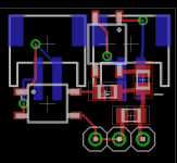
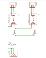
I have created a separate PCB that will be mounted straight on my bias trimmer position on the pcb. I've attached screenshot(s) of what that part looks like at the moment. It has two control lines and two separate SMT opto-isolated relays to allow for a summer/winter bias level setting. Can of course use just one of those and leave the 2nd unpopulated. The goal was to use low EMI opto-isolated relays and ensure that the bias current path is still as short as possible. Use NC relay contacts, open them after appropriate delay. That way if bias control circuit fails or is off for whatever reason, the amp will start with very low bias but still be 'working'.
When I'm done with a design I'll share details of what I'm doing and offer a short run of PCBs for DPS-600 + The Wire users.
It should be fairly easily adapted to other uses and leave out the bells and whistles that I've put in mostly for myself and may not be of interest to everyone.
At the moment the design includes pcb mount tx, 3.3V reg, automatically selecting summer/winter bias setting based on ambient, automatically setting the bias high after a turn on delay, temp sensors for each heatsink, mute control ...
It has inputs for momentary and tactile switches and circuit for latching/toggling these, rather than 'normal' switches because I'm vain and like a nice switch.
I put a 'block diagram' on the last few pages of all of the extra stuff I'm wanting to do, the point is that if there's something missing from that list that you'd like to be able to do then speak up now and I'll try to incorporate it in the pcb design I'm already working on
Cheers,
Chris
I have a schematic I am working on for the control side of things. Mostly it should work how it is, I am just adding things like front panel LED and rechecking a few bits and pieces before starting layout...
I have created a separate PCB that will be mounted straight on my bias trimmer position on the pcb. I've attached screenshot(s) of what that part looks like at the moment. It has two control lines and two separate SMT opto-isolated relays to allow for a summer/winter bias level setting. Can of course use just one of those and leave the 2nd unpopulated. The goal was to use low EMI opto-isolated relays and ensure that the bias current path is still as short as possible. Use NC relay contacts, open them after appropriate delay. That way if bias control circuit fails or is off for whatever reason, the amp will start with very low bias but still be 'working'.
When I'm done with a design I'll share details of what I'm doing and offer a short run of PCBs for DPS-600 + The Wire users.
It should be fairly easily adapted to other uses and leave out the bells and whistles that I've put in mostly for myself and may not be of interest to everyone.
At the moment the design includes pcb mount tx, 3.3V reg, automatically selecting summer/winter bias setting based on ambient, automatically setting the bias high after a turn on delay, temp sensors for each heatsink, mute control ...
It has inputs for momentary and tactile switches and circuit for latching/toggling these, rather than 'normal' switches because I'm vain and like a nice switch.
I put a 'block diagram' on the last few pages of all of the extra stuff I'm wanting to do, the point is that if there's something missing from that list that you'd like to be able to do then speak up now and I'll try to incorporate it in the pcb design I'm already working on
Cheers,
Chris
Attachments
Last edited:
Very nice, I've read through the block diagram and thought there's no way I could implement something like that, though a lot of the features are quite desirable. Certainly be intresting to see how you and qusp get on with incorporating these contols...
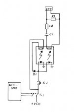
The bias circuit I've penned is simmiler to yours, but with a SPDT relay, a momentery switch as a trigger and the circuits power turned on/off via the dps-600's standby switch... I'll have to find a circuit design program to generate a proper diagram rather than a few hand drawn squiggles.
AND... A big thank you to AP2 for suppling the few bits I managed to break on my dps-600's. Hopfully I can get everything up and running again, and back on track
One thing I hadn't realised before I started digging deeper is this, the DPS600 Enable pin is set after 250ms, which is before the PSU is fully stable. This means that you can't use it to trigger the bias setting delay time. I've got a 555 timer adding an extra delay in my design at the moment. Though you could of course just manually trigger that delay time by hand, but that isn't foolproof enough for my liking (my amp needs to sit in the main lounge room and be totally foolproof for rest of the family ...)
Very nice, I've read through the block diagram and thought there's no way I could implement something like that, though a lot of the features are quite desirable. Certainly be intresting to see how you and qusp get on with incorporating these contols...
The bias circuit I've penned is simmiler to yours, but with a SPDT relay, a momentery switch as a trigger and the circuits power turned on/off via the dps-600's standby switch... I'll have to find a circuit design program to generate a proper diagram rather than a few hand drawn squiggles.
AND... A big thank you to AP2 for suppling the few bits I managed to break on my dps-600's. Hopfully I can get everything up and running again, and back on track
Thank's,
Please, ups notify me, 2nd attempt failed, rest last(one) for deliver the package.
regards
Have organised to collect it in person tomorrow. I was in when the first delivery attempt was made, the driver ignored me on the intercom & had gone by the time I'd made my way down from my apartment
The Wire amps are both working, so it'll be good to get the dps-600's in the same state. Lessons learned I hope
The Wire amps are both working, so it'll be good to get the dps-600's in the same state. Lessons learned I hope
Parcel collected... Cheers Roberto, I like the surprise extras you sent. Thank you!
Well, now i hope you replace well mosfet.
you have to slightly bend the pins of the MOSFET (like the one fitted) and changes the new clip also.
..I hope you're not wrong mount model (as I have sent 2 +2 pairs).
... one pair is for the PWM power stage.
- Status
- This old topic is closed. If you want to reopen this topic, contact a moderator using the "Report Post" button.
- Home
- Amplifiers
- Power Supplies
- DPS-600 fast regulated smps for Wire-Amp