
I don't know a lot about locating malfunctions, but I've grabbed a multimeter and just compared values I got from the left channel to those from the right. First I tested the hFE of the MJ's. They're all ok. Then I just compared resistance values. When I compared the resistance between the collector and base of Q2 (BD139), I got over 10K on the right channel and just about 4K on the left (rising, probably because C4 was charging). The other measurements I took in that area (C4, R6/R7) were consistent. So my guess is that the driver is bad - any thoughts?
The lower resistance would also explain the fact that I measured a quiscent current of over 6A. (also explaining the noise that I heard - it was probably power supply ripple).
BTW, should I open a new thread? This doesn't concern cooling anymore...
edit: output cap is a Philips 4700uF 40 volt
The lower resistance would also explain the fact that I measured a quiscent current of over 6A. (also explaining the noise that I heard - it was probably power supply ripple).
BTW, should I open a new thread? This doesn't concern cooling anymore...
edit: output cap is a Philips 4700uF 40 volt
My DoZ has been revived ") .
.
Since I didn't know much about repairing amps, I e-mailed Rode to ask how and where to begin. His advice was very helpful. I replaced the drivers and used a knife to cut away any possible thin solder bridges between the tracks. I also re-soldered some joints. Afterwards, it turned out the drivers were probably still ok (tested them with a multimeter), so the problem could have been the pcb tracks as well.
I still feel the amp sounds a bit bright, but otherwise it's very good. I think the replaced drivers might have made the sound a little better, less "artificial". Although it could just be the psychological effect of replacing parts.
All in all, I'm very happy with this amp, but always on the lookout to improve things.
.Since I didn't know much about repairing amps, I e-mailed Rode to ask how and where to begin. His advice was very helpful. I replaced the drivers and used a knife to cut away any possible thin solder bridges between the tracks. I also re-soldered some joints. Afterwards, it turned out the drivers were probably still ok (tested them with a multimeter), so the problem could have been the pcb tracks as well.
I still feel the amp sounds a bit bright, but otherwise it's very good. I think the replaced drivers might have made the sound a little better, less "artificial". Although it could just be the psychological effect of replacing parts
.All in all, I'm very happy with this amp, but always on the lookout to improve things
.Hi,
re post 17 and location of 0r1 resistors.
Sounds like you have them in the collector leads.
I have not seen your schematic so please excuse me butting in.
I think they should all (4 of them) be in the emitter leads to ensure better balance and thereby prevent thermal runaway.
What does THERMAL RUNAWAY SOUND LIKE (plopping)?
The 15003/4 are 20 amp devices, if one did overheat it is possible that the gain could drop to about about 4 or 5 as it approached it's current limit. Then it would draw well in excess of 1A through the driver & this may fail first.
regards Andrew T.
Hi,
re post 17 and location of 0r1 resistors.
Sounds like you have them in the collector leads.
I have not seen your schematic so please excuse me butting in.
I think they should all (4 of them) be in the emitter leads to ensure better balance and thereby prevent thermal runaway.
To make things more clear, the attached file contains the schematic.
The differences between this and the "standard" DoZ are:
- C6 is 100uF instead of 470uF (the semi-final DoZ had 100uF).
- No Zobel network (I read many people had problems with this, so I decided to leave it out).
- C5 isn't included (but the power supply contains two Sprague 37000uF caps per channel, so that ought to be enough).
- 4 MJ15003's instead of 2 2N3055's, and resistors to divide the current equally.
What does THERMAL RUNAWAY SOUND LIKE (plopping)?
The 15003/4 are 20 amp devices, if one did overheat it is possible that the gain could drop to about about 4 or 5 as it approached it's current limit. Then it would draw well in excess of 1A through the driver & this may fail first.
regards Andrew T.
I don't think this is the case, as the plopping didn't get worse over time (while the amp was heating up). In fact, it seems to be gone now, so it probably had something to do with the malfunction.
Attachments
Hi
your collector resistors allow you to measure the current in each output leg & not much else. Short them out after you have checked all your operating conditions.
I cannot read parts of your schematic but it looks like the emitter resistors are in the wrong place and doing nothing to improve current balance.
You need a resistor in each emitter lead and you can then discard the common resistor in the output tails.
I'm guessing that tighter matching of the new MJL15003 are balancing your current at the moment but slight heating say due to a change in ambient temperature could set up soa failure again.
regards Andrew T.
Now I'm confused. Rod says this about the resistors:
The example he gives uses PNP transistors, while the MJ's are NPN. But I would think it wouldn't make that much of a difference, since collector current is roughly the same to emitter current.
I didn't really match the MJ's. I ordered 10 of them, because of a discount. I then picked 8 with the closest hFE, and tried to spread the remaining variance among the channels and push/pull sections.
EDIT: Stupid me, I overlooked it! the 0R1 resistors in Rod's example actually are in the emitter leads. But will it make much of a difference? And what about the 0R22 resistor?
The 0.1 Ohm resistors shown in Figure 4 ensure that each transistor carries the same (or at least roughly equal) current. Without them, the transistor with the higher gain (or the lower emitter-base voltage Vbe) will take the majority of the current. This will cause it to get hotter than the "lesser" transistor, which in turn increases its gain further and lowers Vbe even further, which means it will get hotter, and so on. This is all standard stuff in amplifier design. The 0.22 ohm resistor is used to stabilise bias current and introduce local feedback. These must not be omitted.
The example he gives uses PNP transistors, while the MJ's are NPN. But I would think it wouldn't make that much of a difference, since collector current is roughly the same to emitter current.
I didn't really match the MJ's. I ordered 10 of them, because of a discount. I then picked 8 with the closest hFE, and tried to spread the remaining variance among the channels and push/pull sections.
EDIT: Stupid me, I overlooked it! the 0R1 resistors in Rod's example actually are in the emitter leads. But will it make much of a difference? And what about the 0R22 resistor?
starbase218 said:Now I'm confused. Rod says this about the resistors:
The example he gives uses PNP transistors, while the MJ's are NPN. But I would think it wouldn't make that much of a difference, since collector current is roughly the same to emitter current.
[...]
EDIT: Stupid me, I overlooked it! the 0R1 resistors in Rod's example actually are in the emitter leads. But will it make much of a difference? And what about the 0R22 resistor?
It will make a big difference. When in the emitter lead, an increase of current in that one transistor will cause higher voltage drop over the resistor, decreasing the base-emitter voltage so the transistor will conduct less and stabilize the current. If the resistors are put in the collector lead instead the voltage drop will still increase (almost the same current) but it will not cause the Vbe to drop so no better load sharing there.
In Rods schematic the 0R1 resistors are used to get better current sharing between the output transistors. The 0R22 resistor in the example is used to decrease the temperature coefficient of the output stage, and is not needed in your circuit because of the different output stage topology.
Move your 0R1 resistors from the collectors to the emitters and ditch the common 0R22 resistors. They are not needed, the 0R1s are already doing their job when the output stage is connected like that.
Good luck!
*Sigh*, guess this is beginners anti-luck... but if it reduces or stops thermal runaway, I'll go for it .
About the schematic: I did the editing in MS Paint, but apparently some apps can't cope with the color settings of that program. I now converted it to 8-bit color, which should solve the problem. So here goes...
And yet another question: how much power would the resistors actually need to dissipate? I set the Iq to 1.5A, and the voltage is about 33 volts (16.5 volts per side). I calculated 0.225 watts maximum (P = I2*R = 2.25*0.1), so ordinary 0.25W resistors could do the job. But since I'm not to sure... could someone confirm this?
I actually got the idea to build this amp from http://diyaudio.8m.com/. I e-mailed this guy to ask the same question, and he said he used 5 or 10W resistors, so now I have 10W resistors, which might not be neccesary at all... ?
Also, please excuse my ignorance on some aspects of electronics. I have taken a course in electronics and have some basic knowledge, but otherwise I'm a complete noob.
And thank you for all the help so far.
.About the schematic: I did the editing in MS Paint, but apparently some apps can't cope with the color settings of that program. I now converted it to 8-bit color, which should solve the problem. So here goes...
And yet another question: how much power would the resistors actually need to dissipate? I set the Iq to 1.5A, and the voltage is about 33 volts (16.5 volts per side). I calculated 0.225 watts maximum (P = I2*R = 2.25*0.1), so ordinary 0.25W resistors could do the job. But since I'm not to sure... could someone confirm this?
I actually got the idea to build this amp from http://diyaudio.8m.com/. I e-mailed this guy to ask the same question, and he said he used 5 or 10W resistors, so now I have 10W resistors, which might not be neccesary at all... ?
Also, please excuse my ignorance on some aspects of electronics. I have taken a course in electronics and have some basic knowledge, but otherwise I'm a complete noob
.And thank you for all the help so far.
Attachments
It'd be best to use at least 5w resistors for the emitters....better safe operating area. I made a 50wpc DOZ a while ago, 52v rail and 3A bias. Nice amp. I'm gonna go for a higher power one soon i think  I used 2sc5200's for output transistors, i used 8 per channel plus i used them as driver transistors as well. I think i used the MPSA something as the small driver transistors. Anyway, get some big fat heatsinks, and a big output capacitor too. have fun!
-Matthew K. Olson
I'm gonna go for a higher power one soon i think I used 2sc5200's for output transistors, i used 8 per channel plus i used them as driver transistors as well. I think i used the MPSA something as the small driver transistors. Anyway, get some big fat heatsinks, and a big output capacitor too. have fun!-Matthew K. Olson
Tschrama: Why should I use 0R22 resistors instead of 0R1? (note: I already know the schematic is errorous, I attached it because the GIF image I attached earlier didn't display correctly).
Mattyo5: 50wpc in Class-A and you want more power? What massive heatsinks do you have to keep things cool? (pics?)
Mattyo5: 50wpc in Class-A and you want more power? What massive heatsinks do you have to keep things cool? (pics?
)Heatsinking is no problem....house wiring to handle those toroids i'm using...thats an issue. hehe FIRE
I really want to have a fairish comparo between Aleph 2 and DOZ... just for the heck of it. Of course, its a wee bit expensive experiment, but in the end,
here's a pic of the heatsinks, this was my first DOZ at about 50wpc, each sink dissipates 150 watts without fans
this became a stereo amp, my aleph 2's will look similar but be monoblock 75lb monsters
-Matthew K. Olson
FIRE I really want to have a fairish comparo between Aleph 2 and DOZ... just for the heck of it. Of course, its a wee bit expensive experiment, but in the end,
here's a pic of the heatsinks, this was my first DOZ at about 50wpc, each sink dissipates 150 watts without fans
this became a stereo amp, my aleph 2's will look similar but be monoblock 75lb monsters
-Matthew K. Olson
Attachments
DoZ heatsinking
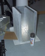
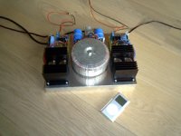
See attached my DoZ project.
It runs hot since it dissipates 68Watts per channel. The heatsinks are relatively small but actually the whole construction (40 volts times 1.7A quiescent current) radiates heat (the base plate is made from 4mm aluminum) even the toroid top plate warms up nicely. Soon, I will put it in a full metal enclosure that will add additional heatsink 'mass'. No problems until now after approx. 600 hours of playing. What do you think of this approach?
DocLorren
Attachments
Its better if the heatsinks were turned upright, so the fins could have airflow up through them, as you have it, its close, but the air cannot flow up through them from the bottom. Otherwise, should be fine Heatsink orientation isn't easy to get right sometimes b/c its convenient to have it more like you have it, or oriented in a different direction (See Nelson Pass Volksamp 30)
-Matthew K. Olson
Heatsink orientation isn't easy to get right sometimes b/c its convenient to have it more like you have it, or oriented in a different direction (See Nelson Pass Volksamp 30)-Matthew K. Olson
DocLorren: Looks nice! Are those Fischer SK34 heatsinks? I use the same, only 4 of them (2 transistors per heatsink, 2 heatsinks per channel), they're 10 cm high. Right now they're not mounted to the case (which is made of steel with an aluminium front plate). If relocating the 0R1 transistors helps enough to counteract thermal runaway, I'll just mount them to the case upright. If not, I'll mount the sinks with fins horizontally and leave room for some fans (like I mentioned earlier) in between the heatsinks.
megajocke: I'm going to relocate them that way if I have the time (I'm a little busy right now).
megajocke: I'm going to relocate them that way if I have the time (I'm a little busy right now).
DoZ heatsinks
Starbase, thx for your comments.
The heatsinks are from Conrad.
http://www1.nl.conrad.com/scripts/w...er_js=Y&shop=A_B2C_NL&p_init_ipc=X&~cookies=1
I tested for thermal runaway in a situation very close to what the final construction would be like (same amount of aluminum to dissipate heat) and let it warm up for 3-4 hours. The quiescent current stayed within 20 mA of the aimed 1.7A. I would therefore say it is stable. In practice (much more important) it does not seem to experience any problem by running hot. By the way, Rod E. himself acknowledges it becomes hot. Well, what do you expect? We are running Class A here!
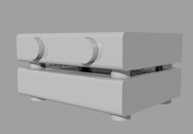
Below find the CAD pictures of the complete DoZ with DoZ pre-Amp. I will probably finish the casings next month. A true and worthy D-o-Zen minimalismistic design! Stay tuned...
DocLorren
Starbase, thx for your comments.
The heatsinks are from Conrad.
http://www1.nl.conrad.com/scripts/w...er_js=Y&shop=A_B2C_NL&p_init_ipc=X&~cookies=1
I tested for thermal runaway in a situation very close to what the final construction would be like (same amount of aluminum to dissipate heat) and let it warm up for 3-4 hours. The quiescent current stayed within 20 mA of the aimed 1.7A. I would therefore say it is stable. In practice (much more important) it does not seem to experience any problem by running hot. By the way, Rod E. himself acknowledges it becomes hot. Well, what do you expect? We are running Class A here!
Below find the CAD pictures of the complete DoZ with DoZ pre-Amp. I will probably finish the casings next month. A true and worthy D-o-Zen minimalismistic design! Stay tuned...
DocLorren
Attachments
Well, I got around to it and re-wired the amp so that the resistors are in the emitter leads. And.. it does stabilize at around 43C with 1.35A quiscent current (I wrote down the current and temperature every 5 minutes for 1.5 hours after it stabilized). But after I closed the case and put the amp back in my rack, it heated up further. If closing the case allready makes such a difference, I figure the margin I have is very, very small.
So I'll probably buy some fans after all, and use a resistor and maybe a thermistor to keep the noise down.
So I'll probably buy some fans after all, and use a resistor and maybe a thermistor to keep the noise down.
Hi,
If you check out the manufacturers K/W graphs vs. what Conrad claims in their catalog or website there are quite a few discrepancies. SK34 10cm is more like 0.9K/W instead of Conrads claim of 0.75K/W if you check Fischer's graph on page A54 of this pdf. Same thing for the other heatsinks in the Conrad catalog.
Take
- Status
- This old topic is closed. If you want to reopen this topic, contact a moderator using the "Report Post" button.
- Home
- Amplifiers
- Solid State
- DoZ cooling