do you know what should be the output on the transformer? 32V AC? also I would like to know What each T(*) means as a connection. There is also a missing connection on the right between Q26 and R49. And a floating connection D6, D10, E3, E4( is that ground?
thank you,
Cristian
Hi, Cristian.
Once upon a time, my son had one of these amplifiers. And it sounds wonderful, especially in the midrange.
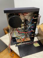
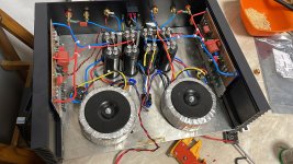
I did opened it but I do not remember too much of what I found inside. Two transformers, I guess 500VA eatch and a heavy RIFA capasitor bank. I do not know the voltage. If you look closer into this forum, you`ll find several pictures. Google is also helpful.
I have never seen a reliable schematic. All the ones I`ve seen on the net are flawed and will not work.
And if you want to clone it, you first have to get the original outputs, BD245/246. I think you will fail already there...
There is no compensator capacitor in the amp. The high Cob of the output transistors makes the amp stable. So you need slow trans with high Cob. Replace them with faster, and you will get a splendid oscillator.
Q26, R49 etc. are ment to be part of a inrush current limiter.
The Ds and the Es are the power suppy. D=Diode. E=Electrolytic capasitor.
T1=Positive power
T2=Input
T3=Output
T4=Negative power
T5-T8=AC in
If you want the DOXA sound at home, I will recommend you to buy a used one. I don`t know if they are available where you live, but they show up from time to time in Norway on the used marked.
I don`t know if this was any help for you, but if you never have heard the "Doxa sound" you have missed something. There are better overall sounding amplifiers out there, but the Doxa sound is remarkable.
Regards
Hi,
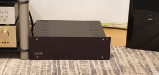
That does not at all look like a standard early Doxa 70
Maybe it's an early version or a heavily modified.
I have a couple of Audio 60 amp's that are fairly close while not identical in design.
Also on these the year of manufacture should be on the PCB.
Unlike the later Doxa 70's these are with NEC Ring-emitter power transistors which are very fast, Ft 60Mhz.
The zobel network across the output is a must and the resistor must be 5w. I remember many years ago having had to substitute for a 2 or 3w resistor and it would emit a puff of smoke whenever the AGI Preamp volume was lovered
Wonderful sound btw.
Would expect roughly 32vac on the Doxa, it's 28v on the Audio60 transformers. I would be very careful going much higher on this circuit.
Last edited:
I cannot find a schematic on this amp, finally I user dual 35V-0-35V 300VA transformers with an upgraded filter capacitor network. The amp is running quite hot now and I am pretty sure the amp is biased to high. I have 2 pots on each amplifier module, i suppose one is for dc and one is for bias. I do not know which one does what and I do not want to blow something up. Also I do not know where to measure the bias to set it up and at what value.
Thanks to kimschips you can get some DOXA schematics at my website: Home - Audio-Circuit.dk
Just click on "Schematics" in the left side menu.
Thanks a lot, Kim
you saved me twice today, be thanked here
This is not a DOXA 70SE.
Most likely this is a DOXA 70 Mk1. (if there is not any secundary power supply for the input stage).
DOXA 70 Mk2 has a regulated on board power supply for the front end.
And a tatally other schematics as pointed out in my previous posts.The output power are about 70 W as indicated by the mod. number.
Regards
Doxa 70 schematic
I pulled this schematic from one of the channels on my Doxa. How would I go about setting the bias and DC offset on this amp? There are 2 VR on the board. VR1 - 50k and VR2 - 200ohms. Where should I measure to set the bias and what value it should be?
thanks
I pulled this schematic from one of the channels on my Doxa. How would I go about setting the bias and DC offset on this amp? There are 2 VR on the board. VR1 - 50k and VR2 - 200ohms. Where should I measure to set the bias and what value it should be?
thanks
Attachments
Hello, anyone that can help with this?Doxa 70 schematic
I pulled this schematic from one of the channels on my Doxa. How would I go about setting the bias and DC offset on this amp? There are 2 VR on the board. VR1 - 50k and VR2 - 200ohms. Where should I measure to set the bias and what value it should be?
thanks
That`s right, ZM.
But the schm in #16 is not the correct schematic for the actual amp.
In fact this schm is incorrect and is referring to DOXA-70 SE or something similar. But the picture in #27 is a DOXA 70 and most likely MK2 edition, and that is a totally other construction.
Yes, there are a lot of confusion regarding the Doxa models, I do not have the compleate overview, but I have some idea about some of them.
I hope I will get some time during the weekend to restore old memories and dig into old papers...
rgds
Hi.
By looking closer to your pictures and and comparing them to the my notes I found, this amp is a Doxa 70 Mk1.
This have not any regulated PS for the input circuits as Mk2 have, 3 output pairs and 4 pairs on the later one.
If there are any other differences, I don't know.
My knowledge to the Mk1 is limited.
But if you look at the PCA, you'll find two trimmers.
The one closest to the output is the Iq and the other one close by, is the Offset.
Put a V-meter over one of the emitter resistors and one at the output to gnd with no speaker connected, and adjust the two pots for the desired values.
Good luck!
rgds
- Home
- Amplifiers
- Solid State
- Doxa 70 Se Schematic??