Hi Gregg, do you think that is possibility of dry solder job was causing the problem? Anyway it is great to see you helping to solve the issues. Cheers!
It still could be a dry joint but its strange that the right input tube shuts down the El34's. The only thing I can see that would do that is the G2 supply for the EL34's being pulled down and dropped across the 10K, assuming of course that its a 10K and not the wrong value. The only way this could happen is if the anode resistor on the right input tube was wrong..we will have to see.

There could also possibly be tube problems. As with all things its difficult at a distance when you are there you can do loads of tests in a few minutes.
It would possibly pay the OP to re-solder all connections.
Regards
M. Gregg
Last edited:
The right driver input tube was a 82k resistor. I guess have to check through the correct value of the resistors.It still could be a dry joint but its strange that the right input tube shuts down the El34's. The only thing I can see that would do that is the G2 supply for the EL34's being pulled down and dropped across the 10K, assuming of course that its a 10K and not the wrong value. The only way this could happen is if the anode resistor on the right input tube was wrong..we will have to see.
There could also possibly be tube problems. As with all things its difficult at a distance when you are there you can do loads of tests in a few minutes.
It would possibly pay the OP to re-solder all connections.
Regards
M. Gregg
The right driver input tube was a 82k resistor. I guess have to check through the correct value of the resistors.
Do you remember the OP said he had a few spare parts?
I could be on the wrong track but I don't see how the input tubes can shut down the EL34 bias any other way except G2 supply.
And caused by the right input tube..there could be multiple faults but you have to start somewhere..
Regards
M. Gregg
Last edited:
Oh yes he mentioned he has a spare resistor that was left over.Do you remember the OP said he had a few spare parts?
Regards
M. Gregg
Oh yes he mentioned he has a spare resistor that was left over.
As soon as the OP removed the input tubes the bias on the El34's came up and gave the correct voltage across the cathode resistor's..He put the left input tube in and the circuit was unaffected..he put the right tube in and the El34's shut down.
Regards
M. Gregg
Probably he got to check his right input driver wiring connections and all the resistors values. Did he confirmed the EL34 tube is good or faulty.
It was a bit hard to understand to be honest, But it seems that with the right tube removed both EL34's are running bias current..but there was something strange that made me think there was an issue where one of the tubes showed over current then seemed to clear.
The first thing is to find the reason the right tube shuts down the el34's..once that's cleared then there can be other issues but we need to focus on getting it up and running first.
Regards
M. Gregg
How about the right input driver tube is faulty?It was a bit hard to understand to be honest, But it seems that with the right tube removed both EL34's are running bias current..but there was something strange that made me think there was an issue where one of the tubes showed over current then seemed to clear.
The first thing is to find the reason the right tube shuts down the el34's..once that's cleared then there can be other issues but we need to focus on getting it up and running first.
Regards
M. Gregg
How about the right input driver tube is faulty?
Then you would have to work out if the 82K was shorted to ground what would the voltage drop across the 10K be, and would it drop enough to completely shut down the bias..of course if the anode resistor was a low incorrect value that would do it but this is just conjecture without actually knowing the situation.
Its like if the 10k was actually 100K that would do it..the driver tubes would draw enough current to drop the voltage across the 100K..
So you are up against an unknown build..and testing against a circuit diagram which you hope matches the built circuit you are testing with no build errors.
Regards
M. Gregg
Last edited:
Hopefully he will check it again and come back with some info. Otherwise quite difficult to figure out. Thanks Gregg for the time to assist him.Then you would have to work out if the 82K was shorted to ground what would the voltage drop across the 10K be, and would it drop enough to completely shut down the bias..of course if the anode resistor was a low incorrect value that would do it but this is just conjecture without actually knowing the situation.
Regards
M. Gregg
Hopefully he will check it again and come back with some info. Otherwise quite difficult to figure out. Thanks Gregg for the time to assist him.
Hopefully we can get it up and running this is team work...
There is nothing worse than having a situation like this and not knowing where to start..
Someone may see something different and be able to help out..
Regards
M. Gregg
Folks, I really appreciate all this help. I am a complete newb dealing with valve electronics but have some experience of fault finding and generally building stuff without picking up wrong end of soldering iron I will get back on this tomorrow. So far I have two sets of input valves to play with but only one set of el34s. It is also annoying that it did sort of work when I first powered it up. I have been looking. For a pinout of the input valves just to check the schematic is correct. I will also check the value of the resistor in the power supply and let you know tomorrow.
Thanks again folks
Ps give Steve Jobs a miss, a really disappointing movie��
I will get back on this tomorrow. So far I have two sets of input valves to play with but only one set of el34s. It is also annoying that it did sort of work when I first powered it up. I have been looking. For a pinout of the input valves just to check the schematic is correct. I will also check the value of the resistor in the power supply and let you know tomorrow.Thanks again folks
Ps give Steve Jobs a miss, a really disappointing movie��
Whats happening with the heater wiring on the input tubes?
The photo seems to show the anode of the one input valve connected to the heater wiring..I guess its the photo the orange wires are the heaters correct?
The yellow capacitor connects to the anode of the tube and the anode resistor then to the orange wiring..
On the other side this doesn't happen because the heater is looped from the other input valve..
so what is happening at this point?
Check both the heater wiring and trace the supply from the 10K to each anode resistor.
_________________________________________________________________________________
Trace choke to 10K>>>>to 47uF>>>>to 82K on each valve>>>to anode.
There should be no other connections. The anodes of the input valves to the yellow coupling caps nothing else.
Make sure the 47uF is the correct way round negative to Gnd. (+ to the 10K).
_________________________________________________________________________________________
Where is the centre tap of the heater winding on the transformer going its should be Gnd?
You have two orange wires with a centre tap shown on the drawing which goes to ground this gives 3.15 from each orange wire to Gnd.
Looks like the black wire in the middle of the two orange wires..
__________________________________________________________________________________________
I assume the large green resistor in the middle is the 10K? its should not be resting on the wiring..just for interest.
Regards
M. Gregg
Last edited:
If the above is true,
You have grounded your G2 supply for the EL34's through the heater winding for the input tubes creating a volt drop across the 10K and then modulated it with 50Hz.
So if the correction works its 2/10 see me after class and do 100 lines I must not connect my B+ supplies to ground via the heater winding..
Regards
M. Gregg
Oh yes I see the heater orange wiring was connected to the 82k resistor. Gregg, I think you have spotted the mistake.If the above is true,
You have grounded your G2 supply for the EL34's through the heater winding for the input tubes creating a volt drop across the 10K and then modulated it with 50Hz.
So if the correction works its 2/10 see me after class and do 100 lines I must not connect my B+ supplies to ground via the heater winding..
Regards
M. Gregg
sorry folks heater wire not connected to anything apart from heater choke to 10K to 82K to valve meters out the same each side on resistance. I checked the valve that was in right side for internal short but nothing meters except heater pins. what i did do was trim some ends on the right input as I noticed they were close and the socket moves. i also replaced input cable so now I have left channel working. Right channel still dead.
choke to 10K to 82K to valve meters out the same each side on resistance. I checked the valve that was in right side for internal short but nothing meters except heater pins. what i did do was trim some ends on the right input as I noticed they were close and the socket moves. i also replaced input cable so now I have left channel working. Right channel still dead.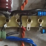
Its a sneaky red wire coming from the positive of the 47 uf cap ! I did find a short, the leg of the 220K was touching a ground. That set the left channel working but distorted so I swapped input valves and right channel started working and left went dead so swapped both input valves and right channel still working left channel ded then found pin on RCA of new signal leads had broken off so currently replacing RCA on Chassis as I can't get pin out of old one and I guess another shopping trip for another new input lead!
- Status
- This old topic is closed. If you want to reopen this topic, contact a moderator using the "Report Post" button.
- Home
- Amplifiers
- Tubes / Valves
- Douk EL34 Amp kit