Flip the board over and measure resistance between pin 4 of A2L and the capacitor beside it to see if they are connected. If not there is a break in that trace. If they are connected there is a break in the trace between the cap and A3L.
Once you figure out which trace is broken have a close look at it and see if you can see where it is. If there's a burn somewhere something shorted and overloaded it. If you see a tiny scratch or crack it was likely a manufacturing defect. Sometimes the trace is eroded away during etching too leaving a round hole though it, the solder mask does a great job of hiding it. Either can be repaired, but it would be wise to throw out any op amp that may have been plugged into those sockets.
There is continuity between A2L fourth pin and capacitor. After further inspection it seems that the trace between the cap and A3L is somewhat altered, I need to desolder the cap. I'll do so in an hour or two.
Thank you for your help, I wouldn't be able to do much without you.
How can I fixe a damaged trace?
If it's just got a small crack you can scrape the soldermask off and blob some solder over it. If it's a stubborn break that can't be fixed that easily solder a jumper wire between the caps on A2L and A3L on the bottom side of the board. Glue the wire in place after so the wire doesn't fall off in the distant future.
Hey there,
I managed to repair the broken trace (V- between caps A2L / A3L) or so did I think.
I'm only getting 17v instead of 34v when I measure between pin 8 and 4 of A1L and A2L.
I wonder if both V- and V+ traces are failing me on A2L.
Any idea on how to get 34v on both sockets ?
I managed to repair the broken trace (V- between caps A2L / A3L) or so did I think.
I'm only getting 17v instead of 34v when I measure between pin 8 and 4 of A1L and A2L.
I wonder if both V- and V+ traces are failing me on A2L.
Any idea on how to get 34v on both sockets ?
Sounds like you may have connected the jumper to the wrong point. You can verify your rail voltages by measuring between each and ground.
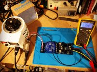
Progress…
This is my second post to this thread, and I’m coming up on a month since acquiring these boards. I am finally making progress on my build. It seems the supply houses are short on supply of many things, but I have managed to find nearly everything.
In addition to this preamp, I am also building Douglas Self’s Signal Transfer unbalanced phono preamp. That project is taking precedence as it is the more pressing need in my system right now. I hope to have the phono preamp running through my BA2018 line stage in the next week, as long as the last few remaining parts arrive to complete it.
I found that the PSU board Carl is supplying here is ideal for the phono preamp too. Good thing I bought two of Carl’s kits! So this PSU is really going to that use, and I’ll start building the second one for this line stage project…
Attachments
Sounds like you may have connected the jumper to the wrong point. You can verify your rail voltages by measuring between each and ground.
Hey jwilhelm,
Im not getting any continuity between pin 4 on A2L and pin 4 on A3L, yet I soldered a wire between A3L left capacitor and A2L right capacitor / A2L pin 4
No voltage on pin 4 on A1L and A2L, no voltage on A3L left capacitor (bottom pin) while get get +17 on the same capacitor top pin and voltage on A3L pin 4.
Thank you for your continued help.
Last edited:

Thank you so much for the advices and this diagram which I was desperately looking for.
I'll try this by the end of the week.
Thank you again for the time spent on helping me.
I'll try this by the end of the week.
Thank you again for the time spent on helping me.

You’re supposed to add a 22uF tantalum capacitor there, I don’t think it’s mandatory but it helps fighting oscillation.
If you search for « tantalum » you’ll find some posts about it.
If you search for « tantalum » you’ll find some posts about it.
You’re supposed to add a 22uF tantalum capacitor there, I don’t think it’s mandatory but it helps fighting oscillation.
If you search for « tantalum » you’ll find some posts about it.
Ah, okay - That’s where the tantalum cap goes. I did find that part of the thread, but didn’t walk the thread carefully enough to realize this is where it goes.
Many thanks Mnk21!
Glen
You’re supposed to add a 22uF tantalum capacitor there, I don’t think it’s mandatory but it helps fighting oscillation.
If you search for « tantalum » you’ll find some posts about it.
It is not a mandatory but it is a vital part.. see TI note page 5
"TheTL750L,TL751L series are low drop out regulators. This means that capacitance loading is important to the performance of the regulator because it is a VITAL part of the control loop"
Also see post # 1211
Attachments
Last edited:
The capacitors to the right side of the op amps are the negative rail side. You need to connect them, not the left to right. I've attached a photo of the negative rail trace.
Hey Jwhilhelm, Hey guys
Main board is now fixed all sockets read 34V but the IO board issue I had before is still there unfortunately...
As soon as I connect the IO board, voltage drops from 17v to 4,5V (measurement taken on power input on the main board).
The 47uf capacitor reads 2,50v, I added a tantalum, and a zener instead of the top BC550 to no avail.
Any idea to troubleshoot it?
Last edited:
Make sure the orientation of the ribbon connectors is correct. The stripe on the cable should be at the same end as the square pad on the board on both ends. Also make sure the correct connections are used. The preamp board should plug into the connector at the end of the input board. The connector towards the center of the input board goes to the switch.
These were double checked, I soon as I take the 12V sw jumper out I get the correct voltage.
Might it be linked to the 12v regulator since the voltage drop is more or less 12v ?
Might it be linked to the 12v regulator since the voltage drop is more or less 12v ?
Something is pretty much dead shorted which is why I thought of the connections first. Reversing the power connections is the fastest way to cause things to short.
Check the diodes on the relays of the output connectors for shorts and correct orientation. Measure the resistance between the input of the regulator and ground. If it's very low the regulator is likely shorted.
Check the diodes on the relays of the output connectors for shorts and correct orientation. Measure the resistance between the input of the regulator and ground. If it's very low the regulator is likely shorted.
I replaced the diodes and measured a 4k resistance between input and ground of the regulator. The capacitor still doesn't charge up to 5v.
Sounds like the regulator is shorted.
With the regulator removed now would be a good time to verify everything else is correct. Measure the voltage between the regulator input and supply ground. It should be +17V there, pay attention to polarity to make sure it's correct. Do you have a bench supply? If so with the regulator removed apply 12V to the output relays one at a time to verify they engage and there's no problem there.
With the regulator removed now would be a good time to verify everything else is correct. Measure the voltage between the regulator input and supply ground. It should be +17V there, pay attention to polarity to make sure it's correct. Do you have a bench supply? If so with the regulator removed apply 12V to the output relays one at a time to verify they engage and there's no problem there.
- Home
- Source & Line
- Analog Line Level
- Doug Self Preamp from Linear Audio #5