I just received the PCBs and I started to solder the components. But in the files that I got I have two different PSU schematics regarding some component values. I attach both of them. Please advise which are the correct values for R5, R6, R9, R10 resistors.
Attachments
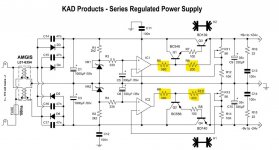
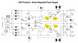
Thank you very much for your quick response.Both work but PSU2 is most correct. Jan Didden suggested the values in PSU2 as an improvement. Thanks Jan.
Is this PSU better than a LM317 supply?Both work but PSU2 is most correct. Jan Didden suggested the values in PSU2 as an improvement. Thanks Jan.
It seems rather artificially overengineered to me. It also doesn't have short circuits or temperature handling. If it had less noise, okay.
If you know how to improve the PSU, I invite you to document your revised circuit on this thread. If your change is worthy members will quickly embrace it and I will integrate it to the PCB.
see jan comments on PSU1 design oversight Post # 1404Both work but PSU2 is most correct. Jan Didden suggested the values in PSU2 as an improvement. Thanks Jan.
I saw them somewhere at Mouser as well: https://www.mouser.at/ProductDetail/490-RCJ-412323
Inspired by the discussion here about an IR controllable version of this preamp, I have started again to think of possible solutions. I have had many ideas which I often discussed with @Carl_Huff (thank you, Carl, for your time - I wouldn't have come this far without your help). Most of the ideas were quickly discarded, and some made it to a design/routing phase. Finally, I implemented a concept which allowed me to re-use the preamp PCB and the +-15V supply PCB:
Some impressions:
Front:

Digipots:

Modified IO board:

Everything combined:

Example splash screen")

So far, I haven't done measurements yet but the preamp sounds good to me (=without audible noise/distortions) which is my primary goal. Nevertheless, there are things left to be done which I will follow up step by step:
Any hints/suggestions/questions are always welcome!
- I designed a PCB to hold MCP41HV51 digipots which fits exactly on the original preamp PCB as a replacement of the mechanical pots. Luckily, I had one of these PCBs already at hand from an earlier try
- The IO PCB needed a few modifications:
- separate grounds for audio/relays
- low side relay switching with an ULN2003
- updated 12V supply
- for my convenience: selectable relay supply (onboard/external) and selectable output delay control (onboard/external)
- As microcontroller I am finally using an Adafruit Grand Central M4 Express which can be programmed using the Arduino IDE and many of the Arduino libraries can be used, too. Originally, I had used an Arduino Mega 2560 which caused a lot of headache to me as it turned out to be the source of hizz in my setup.
- I added a small RGB OLED (small enough to fit into a 1U case) and a rotary encoder + switch.
- The digital stuff is powered by a small 5V SMPS.
Some impressions:
Front:
Digipots:
Modified IO board:
Everything combined:
Example splash screen
So far, I haven't done measurements yet but the preamp sounds good to me (=without audible noise/distortions) which is my primary goal. Nevertheless, there are things left to be done which I will follow up step by step:
- Implement the IR control which I had honestly forgotten when designing the front panel
- Implement using the big standby switch
- Cable cleanup
- Implement NVM storage of settings
- ...
Any hints/suggestions/questions are always welcome!
- Home
- Source & Line
- Analog Line Level
- Doug Self Preamp from Linear Audio #5