--- It is supported by understanding the principles of how and why this works. If you disagree with some part of my detailed explanation of that, you should address that directly.
---Look Sy, it was made clear in the article that Andres does not have the test equipment to do that kind of thing. It was also made clear that this was about hotrodding, not space engineering. It is what it is--what-you-see-is-what-you-get, and it's, guess what--FREE! If you want that stuff, I suggest that you build it and measure it and report back to us, instead whining about someone else's effort to achieve something.
On the first part, i believe that your understanding is incomplete. Core saturation at low frequencies is well-known and characterized- I'd refer you to RDH4. Feedback will only make things worse. Data is a better way to make your case than handwaving and repetition.
On the second part, if he (or you) has a computer and a soundcard, that's all that's needed. An interface like Pete Millett's is nice, but a resistive attenuator is 10 cents worth of parts, works fine, and can be constructed in about 5 minutes.
To Gilgy:
--- Yes, you could but since the smiley face presumably does nothing in concert with the other elements of the invention, it would not be seen as better than the mods, without the smiley face. For example, the extraordinary NFB used in the Hotrodded ST-70, allows it to operate in the saturation region of the output transformer, with high fidelity. That works in concert with the other mods to achieve doubled output power with the quality needed.and then, wait for it, painted a smiley face on the volume knob. If I do all these things, can I claim to have invented something new?
To Sy:
If I have been repetitious in this thread, it is only because the posted challenges have been repetitious. Believe me, it's not much fun, having to explain the same things over and over to posters who are too lazy to read the thread, posters who fail to grasp the issue being discussed and posters who misread previous explanations. I agree, that has been rampant here.
Gradual core saturation can be characterized as a nonlinear load placed across the primary of the transformer. Thus it causes distortion by the nonlinearity working against the effective driving impedance at that point. If ordinary feedback is wrapped around the output stage/transformer system, it will reduce distortion by approximately the loop gain. So your statement that feedback will only make things worse, is false. This was shown experimentally with the ST-70A. The output power at 20Hz, measured at the 1% distortion point, went from 13W (stock) to 19W. Looked at another way, 20Hz distortion at half-voltage output went from 0.7% to 0.11%. Most of the improvement was due to the increased NFB. The same mods used in the ST-70A are at work in the Hotrodded ST-70.Core saturation at low frequencies is well-known and characterized- I'd refer you to RDH4. Feedback will only make things worse.
(You get a hyena star.) The technical explanation I used to illustrate the generality of the techniques used was hardly handwaving. If there is a point which you disagree with in that, quote it and say why.Data is a better way to make your case than handwaving and repetition.
If I have been repetitious in this thread, it is only because the posted challenges have been repetitious. Believe me, it's not much fun, having to explain the same things over and over to posters who are too lazy to read the thread, posters who fail to grasp the issue being discussed and posters who misread previous explanations. I agree, that has been rampant here.
Distortions such as hysteresis (particularly at low frequency), which are characterised by significant signal time delay, are not correctible by NFDBK.
On the other hand, there may be some erroneous understanding of the effect of halving the OT impedance and doubling the power. That does not require any further excursion into saturation than before, if the same low freq. spec is observed. The signal current does not cause saturation, the volt-second product of the signal does, and that stays constant here (same low freq, and same peak voltage, only signal current increased)
On the other hand, there may be some erroneous understanding of the effect of halving the OT impedance and doubling the power. That does not require any further excursion into saturation than before, if the same low freq. spec is observed. The signal current does not cause saturation, the volt-second product of the signal does, and that stays constant here (same low freq, and same peak voltage, only signal current increased)
Last edited:
To smoking-amp:
--- Hysteresis does not necessarily imply time delay. Low frequency transformer distortion IS correctable by NFB and the ST-70A demonstrates that fact dramatically.Distortions such as hysteresis (particularly at low frequency), which are characterised by significant signal time delay, are not correctible by NFDBK.
--- If you think something I have said is erroneous, quote it and say why.there may be some erroneous understanding of the effect of halving the OT impedance and doubling the power.
Mmmmh ! ?
For what I understand in OPTs it's a too hi induction (B) that causes iron saturation an thus produces distortion.
This happens at the lowest frequency and at hi power because the induction increases with voltage applied (U) and decreases with frequency (F), something like that:
B = U / F at least for a given core size and excluding "unities match".
So that: if U and F both remain the same, so does the induction.
Only current had increased by a factor of 2 and may overheat somethings.
To avoid that, larger wire should have been used and this needs more room in the bobbin that means a larger bobbin and thus a larger iron.
But not so much because for a given induction you then need less turns . . . and less room !
More than ever, increasing the iron size is not a "magnetic" necessity, just a "mecanic" constraint to have the room for more copper.
My two pence.
Yves.
The technical explanation I used to illustrate the generality of the techniques used was hardly handwaving.
No evidence = handwaving.
Reduction in inductance = lower open loop gain = less feedback. Higher current = more resistive losses = less feedback.
Again, data to support your contention (especially using a couple of different OPTs) would be highly useful.
Hysteresis is caused by avalanching of magnetic domains when the current crosses zero, but does not show up in the signal until that passes its peak. That is time delayed, especially at low signal frequency. NFdbk acts too late to fix the problem, it would have to act earlier than the signal peak to fix it. Instead, it just causes more delayed cascade hysteresis effects.
--------
""there may be some erroneous understanding of the effect of halving the OT impedance and doubling the power.""
"--- If you think something I have said is erroneous, quote it and say why."
You said there were increased saturation effects which the extraordinary NFdbk took care of.
--------
""there may be some erroneous understanding of the effect of halving the OT impedance and doubling the power.""
"--- If you think something I have said is erroneous, quote it and say why."
You said there were increased saturation effects which the extraordinary NFdbk took care of.
Last edited:
To Sy:
--- The term handwaving usually means the debate technique of failing to rigorously address an argument in an attempt to bypass the argument altogether. (from wikipedia) It doesn't mean simply a lack of physical evidence. I have not heard any objection to the arguments I presented regarding the generality of the Supermods™ technique.No evidence = handwaving.
--- We have presented data to support the power claims with the original project and from the lab measurements on a second ST-70 transformer. I totally agree that it would be nice to have this technique tested on various platforms. Would you be interested in cobbling something up? We will present additional results on the Tronola.com site whenever it becomes available.Again, data to support your contention (especially using a couple of different OPTs) would be highly useful.
Power claims are fine (at least for that transformer), but the question is LF distortion and what the harmonic spectrum looks like. I've certainly used OPTs at non-standard ratios (in fact, my current amp is set up that way), but hard experience taught me that running deep bass through them was not a great idea if I wanted to keep distortion low and low order.
I'd be happy to participate but I'm so insanely backed up for projects (line amp with tone controls, mini guitar amp, turntable speed controller, high power pentode amp) that this would be spring of next year at best.
I'd be happy to participate but I'm so insanely backed up for projects (line amp with tone controls, mini guitar amp, turntable speed controller, high power pentode amp) that this would be spring of next year at best.
you mean sounding perfect, as far as the ear can tell.
I mean sounding clean but lifeless much like the 400 watt Carver / Phase Linear system that I just gave away.
For the last 30 years or so many amp manufacturers have engaged in a war of specmanship. With enough open loop gain and feedback it is easy to put more zeroes after the decimal point in the THD spec when measured on the bench using a pure sine wave. Not many of us like to listen to pure sine waves, we prefer music. Often an amp that measures near perfectly sounds dull, lifeless and boring. It may be a more perfect sound, and if you llike it, then pile on the GNFB. The majority of tube amp builders build amps to get the sound that you can't get at Best Buy.
I have referred to the "NFB of an amplifier," in context, to mean the loop gain of the amp (as others here do).
The "NFB of an amplifier" or "amount of NFB" usually refers to the amount of system gain reduction you get when the feedback loop is connected.
If an amplifier has 40 db of total gain measured in db from input to output with zero feedback applied to it (A) then has 30 db of total system gain (Vin / Vout) once the feedback is connected, the NFB of the amplifier (Beta) is said to be 10 db. A zero feedback amplifier does indeed have gain.
My amplifier designs usually use from 0 to 6 db of feedback for triode and UL designs and 6 to 10 db for pentode designs. An amplifier used only for bass may use more. All of them have far more than 0 to 10 db of system or closed loop gain.
Core saturation at low frequencies is well-known and characterized- I'd refer you to RDH4. Feedback will only make things worse.
Core saturation does have a time related component that can not be fixed with feedback. I am currently 1200 miles away from my lab and home computer, but I have scope pictures to illustrate it somewhere.
As an amp goes into clipping its open loop gain begins to drop (more input does not produce any more output) A mild ammount of feedback can delay the transition to clipping providing a tiny bit of headroom, but it can not stop the inevitable. Once the amp clips the open loop gain approches zero and the system hits the rail. How the amp behaves in clipping, and how it recovers from clipping will affect how it sounds, but not how it measures with a sine wave. This is why you need a zillion watts of modern solid state power....so it NEVER clips.
A well designed (no bias shift in clipping, good recovery from clipping) zero feedback tube amp can operate well into clipping on transients without being blatantly obvious to the listener. An amplifier that has a lot of feedback and has a few capacitors in the signal path will have a finite recovery time that can be tens or even hundreds of milliseconds long. Again, this will be heard, but not shown in steady state bench measurements.
As an OPT gets pushed into saturation its inductance drops and its loss increases. Again more input does not produce any more output. Feedback will tend to force more input. There will be a finite time to reverse this condition once the overload is removed and feedback can not correct for this. There will be dsitortion across the entire audible range until the magnetics of the OPT have recovered.
wait for it, painted a smiley face on the volume knob.
But when you cranked the volume all the way up the face would frown.....Oh wait that is your angry neighbors......
I cant see how you can shove More Power through a Saturated transformer at a specific frequency and power--It just Aint Possible....
Seeing that this innovation/update (Its NOT an Invention!) allegedly works, indicates to me that the Saturation-point of the ST70 Tx is NOT the limiting factor (ie--Not Saturating in its original design format and power) thus you are able now to drive it TO the point of saturation and gain power over and above that of the original amp design...
Seeing that this innovation/update (Its NOT an Invention!) allegedly works, indicates to me that the Saturation-point of the ST70 Tx is NOT the limiting factor (ie--Not Saturating in its original design format and power) thus you are able now to drive it TO the point of saturation and gain power over and above that of the original amp design...
but hard experience taught me that running deep bass through them was not a great idea if I wanted to keep distortion low and low order.
I can state (I already have but...) that for SOME OPT's ratioing down (a term that I believe was invented on this forum) can improve the low frequency power handling capabilities provided other conditions are met. The main one seems to be low driving impedance which can be achieved by piling on the global feedback OR using a low Mu triode OR using a pentode with local feedback applied to it. There may be other methods that I haven't explored yet. I'm not done yet.
This technique works exceptionally well with the cheap Ebay sourced Schumaker OPT's that I referred to earlier. It has worked on several other OPT's that I have tried including Single Ended transformers. In fact look at the Hammond 125 series both SE and P-P, look at the chart that comes with them. This is how the manufacturer INTENDED them to be used!
It does NOT work with the cheap Edcor XPP series. In fact NOTHING I found can make these things pass good bass. For $15 (at the time) they aren't going to pass much bass.
It does not work with a pair of Handwound Electronics (David Lucas) 60 watt P-P OPT's that I got on Ebay. These transformers are rather large and have a lot of leakage inductance. They work OK at their rated 6600 ohms, but distort pretty badly above 10 KHz when ratioed down to 3300 ohms. No amount of feedback local or global can fix this. In fact feedback causes the distortion to go UP. I believe this to be caused by excessive phase shift within the OPT.
To smoking-amp:
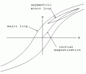
The point we are at could be the top point of the asymmetric minor loop (AML). Now suppose the input signal starts down. The output traces the path to the left on the AML. It does so instantly, in response to the input signal. Notice that the output always goes up, when the input goes up and always goes down, when the input goes down (although not on the same path). No delay.
If we wrap a (unity gain, non-inverting) feedback loop around the hysteresis. The error amp can always push the output up when it wants to and down when it wants to. Thus, it will always make the output match the input, as long as the nonlinearity isn't completely saturated.
So hysteresis in a transformer does not, in itself, cause a time delay and there is no problem wrapping negative feedback around the hysteresis of a transformer. (Of course, there are lots of other issues to deal with, when wrapping NFB around a transformer.)
--- Sorry, but you are confusing nonlinearity with time delay. Lets trace the path of a signal applied to an ideal nonlinearity: In the attached pic, we might be going up the initial magnetization curve. The output responds instantly to the input on the way up. If the input freezes (say, just for a moment) at some point on the rise, the output also freezes at its point, instantly.Hysteresis is caused by avalanching of magnetic domains when the current crosses zero, but does not show up in the signal until that passes its peak. That is time delayed, especially at low signal frequency. NFdbk acts too late to fix the problem, it would have to act earlier than the signal peak to fix it.
The point we are at could be the top point of the asymmetric minor loop (AML). Now suppose the input signal starts down. The output traces the path to the left on the AML. It does so instantly, in response to the input signal. Notice that the output always goes up, when the input goes up and always goes down, when the input goes down (although not on the same path). No delay.
If we wrap a (unity gain, non-inverting) feedback loop around the hysteresis. The error amp can always push the output up when it wants to and down when it wants to. Thus, it will always make the output match the input, as long as the nonlinearity isn't completely saturated.
So hysteresis in a transformer does not, in itself, cause a time delay and there is no problem wrapping negative feedback around the hysteresis of a transformer. (Of course, there are lots of other issues to deal with, when wrapping NFB around a transformer.)
Attachments
The higher slope of the magnetization curve near zero crossing is caused by avalanching of domains. Stopping the signal does not necessarily stop the avalanching, this can overshoot. Your published curve is an average of many loops. Individual loops have statistical variation. Then there are the top/bottom parts of the curve. Here the reduced response is due to a lack of available magn. domains to respond (ie, saturation). To ensure the linear availablility of domains there, one would have to prevent avalanching in the earlier zero crossing region, hence a time delay effect. Using a low source impedance can prevent this by controlling avalanching, but this is best done by local feedback, not global fdbk thru the xfmr. I might also add that the magnetization curve for grain oriented steels commonly used in OTs is much squarer than the graph presented. The effects of domain avalanching are greatly enhanced.
In addition to this, the amplifier itself can have time effects related to capacitor coupling voltage shifts when the magn. saturation causes loss of forward gain and NFdbk compensates during grid conduction.
In addition to this, the amplifier itself can have time effects related to capacitor coupling voltage shifts when the magn. saturation causes loss of forward gain and NFdbk compensates during grid conduction.
Last edited:
To tubelab.com:
As the Hotrodded ST-70 article has demonstrated, core saturation is a gradual phenomenon. Contrary to your statement that only a "tiny amount of headroom" is to be gained by using such feedback, we have shown a large increase in power output, due in part to the use of extraordinary NFB. The ST-70A showed an increase of 46%, which is a substantial part of the power gained with the Supermods version.
In the lab, the ST-70 transformer, limited to 13W at 20Hz in the stock amp, was shown to pass almost 80W at 20Hz, undistorted. That is why the Supermods™ amp can deliver 53W at 20Hz.
--- If there is a true transport delay associated with transformer core saturation, it is short enough that it does not cause a problem with using a lot of feedback at low frequency, as the ST-70A has demonstrated.Core saturation does have a time related component that can not be fixed with feedback...A mild amount of feedback can delay the transition to clipping providing a tiny bit of headroom, but it can not stop the inevitable.
As the Hotrodded ST-70 article has demonstrated, core saturation is a gradual phenomenon. Contrary to your statement that only a "tiny amount of headroom" is to be gained by using such feedback, we have shown a large increase in power output, due in part to the use of extraordinary NFB. The ST-70A showed an increase of 46%, which is a substantial part of the power gained with the Supermods version.
In the lab, the ST-70 transformer, limited to 13W at 20Hz in the stock amp, was shown to pass almost 80W at 20Hz, undistorted. That is why the Supermods™ amp can deliver 53W at 20Hz.
To smoking-amp:
--- The reply (post#118) to tubelab.com applies equally here. Any true delay is such that there is no problem, wrapping lots of NFB around the transformer at low frequency, where the saturation is an issue.Stopping the signal does not necessarily stop the avalanching, this can overshoot.
To Alastair:
So you are exactly right, we ARE now able to drive it much closer to the point of saturation. And by the way, that point is 79W at 20Hz. (Found in the lab.)
--- What we have shown is that low frequency OPT saturation is a gradual effect. So the power limits (set at 1% distortion) at low frequency previously found in ordinary amps like the Eico ST-70, are grossly low. 13W versus 53W at 20Hz.I cant see how you can shove More Power through a Saturated transformer at a specific frequency and power--It just Aint Possible....
So you are exactly right, we ARE now able to drive it much closer to the point of saturation. And by the way, that point is 79W at 20Hz. (Found in the lab.)
- Status
- This old topic is closed. If you want to reopen this topic, contact a moderator using the "Report Post" button.
- Home
- Amplifiers
- Tubes / Valves
- Doubling the power of hifi tube amplifiers