Bigwill's individual tube curves in post #33 show rather sharp cutoffs in the tube currents compared to SGregory's curves in post #38. Perhaps each output tube has a separate local feedback or dedicated LTP driver? GNFDBK would only be concerning itself with the net sum (or difference actually) of the tube currents, so I don't see why too much of that would make the individual tubes cut off so sharply. Poses an interesting question of whether individual local feedbacks might aggravate crossover dist.
Last edited:
Bigwill's individual tube curves in post #33 show rather sharp cutoffs in the tube currents compared to SGregory's curves in post #38. Perhaps each output tube has a separate local feedback or dedicated LTP driver? GNFDBK would only be concerning itself with the net sum (or difference actually) of the tube currents, so I don't see why too much of that would make the individual tubes cut off so sharply. Poses an interesting question of whether individual local feedbacks might aggravate crossover dist.
Each tube in my circuit has its own local feedback, and I also questioned whether or not this would make crossover distortion worse. The feedback signal comes from the anode which DOES see the entire waveform so you'd think in the crossover region both tubes would be working together to minimize the "damage" of the crossover region just before it actually happened....
hmmm!

In a simulation, where the models are exactly matched, that may work. But in a real circuit, the two sides most likely will not exactly agree with each other, so some glitch may be present when one side assumes control exclusively.
Separate Schade feedbacks to the driver plates (or the output grids) would provide this subtle lack of coordination unless the attenuation factors are exactly tuned up to match. Might be interesting to try mismatching the feedback networks slightly in your simulation to see what happens to the distortion spectrum.
On the other hand, individual feedbacks to a driver LTP stage's grids (CCS tail ideally) should automatically self coordinate I would think thru the tail connection.
Last edited:
I think you are probably right. I had a big thing for Schade feedback but I don't think it's quite what you want for AB operation, you want a nice linear composite device made of both halves of the PP pair, not each one trying to be its own voltage source, fighting the other...
Last edited:
DCR and leakage inductance in the OPT primary cause each side feedback to see a different version of the output signal. This would be OK in class A but may cause problems when one side cuts off.
It may help some to try to bias your output tubes for a smooth composite gm curve through crossover. It may also help to somehow combine the feedback from side to side...
With tetrodes the plate resistance is too high for current hogging or "fighting". It's about the feedback.
Cheers,
Michael
It may help some to try to bias your output tubes for a smooth composite gm curve through crossover. It may also help to somehow combine the feedback from side to side...
With tetrodes the plate resistance is too high for current hogging or "fighting". It's about the feedback.
Cheers,
Michael
Last edited:
With tetrodes the plate resistance is too high for current hogging or "fighting". It's about the feedback.
True, but with Schade style feedback a tetrode becomes much like a very low Rp triode!
With two tubes per side you could apply the same feedback to both grids so that they would make a low Rp composite, but not fight each other
On thinking about this some more (separate local feedbacks), I think there is a crossover glitch problem here even with perfectly matched tubes (or tube models). The feedback loop consists of the attenuating feedback resistor network and the foward gm gain of the associated output tube. As the P-P signal tilts back and forth in P-P fashion, the tube gms vary due to their non-linear nature. So there is always a disparity between the two sides when one side hands over control. No amount of tweeking resistor networks can fix this since it dynamically tilts one way, then the other way, always mismatched at hand-over. So class AB needs some driver LTP tail averaging to smooth the two controls out.
Equivalently, only the net signal, and not the individual pieces, need to control things coherently. At least in an outer loop. I could see maybe a set of inner loops that try to smooth the indiviual gm variations into two linear ramps or some function that add up to a constant net gm for the outer loop some how. But how to do this for class AB? (Well, I guess there is already something that does this, it's called Hawksford Error Correction, it just feeds back the error alone at -unity gain)
Equivalently, only the net signal, and not the individual pieces, need to control things coherently. At least in an outer loop. I could see maybe a set of inner loops that try to smooth the indiviual gm variations into two linear ramps or some function that add up to a constant net gm for the outer loop some how. But how to do this for class AB? (Well, I guess there is already something that does this, it's called Hawksford Error Correction, it just feeds back the error alone at -unity gain)
Last edited:
True, but with Schade style feedback a tetrode becomes much like a very low Rp triode!
With two tubes per side you could apply the same feedback to both grids so that they would make a low Rp composite, but not fight each other
Good point, with completely separate feedback it acts like 2 triodes. In this case it might be best to approach class B operation. Or arrange the idle condition such that there is a smooth, ideally constant, gm through crossover.
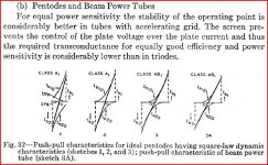
Schade points out the problem with AB triodes in his 1938 paper (page 357 in the journal) - and proposes why pentodes are more suited, also showing the well-known illustration of the mirror-image load line showing best composite linearity.
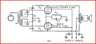
He proposes a class AB design using a phase splitting transformer and voltage summing of drive signal and feedback, which provides the feature of combining the feedback signals from the 2 sides through the transformer common core.
I'm not following you about 2 tubes per side though; 2 tubes in parallel?
Attachments
Last edited:
I'm not following you about 2 tubes per side though; 2 tubes in parallel?
Indeed, I simply meant that two pentodes in parallel with one Schade feedback resistor (to both grids) would result in two tubes that don't hog due to their high Rp, but the net result would be a low Rp composite device
I am off to bed now but perhaps I will experiment with a better local feedback approach tomorrow

"I'm not following you about 2 tubes per side though; 2 tubes in parallel? "
I'm not following that one either.
"I simply meant that two pentodes in parallel with one Schade feedback resistor (to both grids) would result in two tubes that don't hog due to their high Rp, but the net result would be a low Rp composite device"
Seems to me thats the same as just using a bigger tube.
But it does give me an idea for a strange design. Complex though. Two tubes per side. With two LTP driver stages. One LTP driver stage controls one tube on each side, the other controls the other tubes on each side. Each LTP driver takes its feedback from one side of the OT. Symmetrical at least, crazy probably.
How about two tubes per side, controlled in parallel as Bigwill suggested, but with different DC bias on one set versus the other. Then AB crossover occurs in different places for the two sets.
"which provides the feature of combining the feedback signals from the 2 sides through the transformer common core."
Hmm, I'm not seeing any combining of feedback signals in Schades schematic thru the driver xfmr. Although the two sides of the OT should nominally be the same anyway. What seems to be the main problem to me is the disparity in gm when handing over control from one tube to the other. Schade's biasing graphs seem to address that for smoothest net gm.
Last edited:
Hmm, I'm not seeing any combining of feedback signals in Schades schematic thru the driver xfmr. Although the two sides of the OT should nominally be the same anyway. What seems to be the main problem to me is the disparity in gm when handing over control from one tube to the other. Schade's biasing graphs seem to address that for smoothest net gm.
Oh, so right. The feedback signals are subtracted separately from a common drive voltage. There is no feedback current in the transformer.
So if the drive signals are mirrors of each other, the main issue must be the gm bump, which can be addressed by selecting an op point for best composite gm.
I wonder if that's all that's happening here. What happens if the idle current is reduced? Is there a minimum distortion point?
Michael,
Is it safe to assume that even without local feedback (only GNFB), there would be an optimal bias setpoint for minimum distortion.
I was playing around with THD vs. Bias Current when the amp is in AB. I have only really measured THD with bias >60mA on a KT88. At 80mA I found that the THD increased slightly from 70mA. In addition, as expected, max power decreased as a result of reduced b+ (due to PT load).
In addition to turning off compression of the simulation data and all the other tips mentioned previously, you need to set the simulation's time frame such that it starts and stops saving data at the wave's zero crossing point. Otherwise, LTspice will interprete the "partial" wave as distortion.
A good reference is also plotting the FFT of the actual input, which in SPICE software should be ideal. Very often it's not.
A good reference is also plotting the FFT of the actual input, which in SPICE software should be ideal. Very often it's not.
Attachments
- Status
- This old topic is closed. If you want to reopen this topic, contact a moderator using the "Report Post" button.
- Home
- Amplifiers
- Tubes / Valves
- Does anyone have any FFT plots from real Class-AB tube amps?