Re: Does any Power amp have a current limiting device?
Dear Mr. Arthur,
thank you so much for your very kind and valuable reply.
First of all I have to declare my complete ignorance in electronics.
I am trying to learn something but without basic knowledge I have no hope.
And even the basics are really hard to understand for me.
>
Thank you very much Mr. Arthur
Kind regards,
beppe61
Dear Mr. Arthur,
thank you so much for your very kind and valuable reply.
First of all I have to declare my complete ignorance in electronics.
I am trying to learn something but without basic knowledge I have no hope.
And even the basics are really hard to understand for me.
>
Arty123 said:HI Beppe, First off, It is important to see that current is not the only factor: If the amplifier is clipping, the speaker cone is stationary at maximum current, which equates to DC flowing through the voice coil. This will destroy the voice coil, as no cooling is available.
The optimum is a soft clipping characteristic, combined with overvoltage and overcurrent protection.
Have a look at http://www.hypex.nl, they do a number of excellent Class D amplifiers, with all the stuff you'll need to build a complete power amp, with all the protection you'll need for minimal cost. A UcD180 module is only 60 Euros....
As a matter of fact I have already posted questions in the Class D forum about UcD modules as beppe61.
I read great things about these products.
They will be present in a lot of amps at the next CES in USA in January, I understand.
> I built my amp with UcD180's and it sounds better than any Krell I have ever listened to, I have listened to those and Mark Levinson, MacIntosh and numerous others.
What about their driving ability with demanding load ?
I read some reserves about this.
I have Dynaudio speakers. To wake-up the woofers and control them a very powerful amp is mandatory.
Which speakers do you use with UcD180 ?
Have a look at the Class D forum as well, it is full of good advice. Cheers, Arthur.
Thank you very much Mr. Arthur
Kind regards,
beppe61
Workhorse said:
Dear Sir Charles Lehmann,
Absolutely agree on your first point, but I think Mr.Jan Didden and Mikeks wouldn't..agree because they think overbuilding the output stage is wastage of resources and could be cured with SOA limiter[Their opinion not mine]
But I would favour Overkill in output stage in pro-audio amp..
Yes , the switching amps would take anything resistive to highly reactive without any threats, provided an overcurrent protection implemented along them....
sincere regards,
K a n w a r
Dear Sir,
thank you so much for your extremely kind and valuable reply.
Unfortunately the technical discussion is very much beyond my reach.
Anyway I find extremely interesting this your statement:" the switching amps would take anything resistive to highly reactive without any threats ". Very interesting.
Thank you very much indeed.
Kind regards,
beppe61
janneman said:
I think you misunderstood. SOA protection is designed to safeguard the output devices, WHATEVER loads you throw at them. So, if the SOA is set up correctly, no imaginable load will destroy them.
Jan Didden
Thank you Mr Didden.
I am very sorry not to be able to take part in the discussion but I like this idea of SOA protection.
As I understand correctly, this kind of protection can guarantee that the output devices are used up to their maximum performance.
I think it is very much more refined protection system that a trivial current limiting device/circuit.
Am I right ? My knowledge is very limited.
Kind regards,
beppe61
beppe61 said:[snip]I think it is very much more refined protection system that a trivial current limiting device/circuit.
Am I right ? My knowledge is very limited.
Kind regards,
beppe61
Yes and no. The concept is really not that complex. Normally you would feed the voltage across the emitter resistors of the output stage to a transistor base. That voltage is really a measure of the output transistor current Ie (Ie * Re = Vbe of the protection transistor). That transistor then starts to conduct if the current gets too high. You with me so far?
")
The protection transistor is connected to the driver stage, so when it starts to work it will steal drive current and thus limit the output current that will be available. So far so good.
The SOA implementation will take a resistor from the power supply voltage and use it to inject extra current into the protection transistor base. The protection transistor is connected with its emitter to the output, which is close to Ve of the output device. The output transistor Collector is normally connected to the power supply. So, the current injected by the extra resistor is really a measure of the output transistor Vce! (Injected current = Vce/Rinjection).
So, now the protection is activated not only by the output Ie but also the Vce. So, when Vce rises, smaller Ie will already trigger the protection because the protection transistor is 'helped' by the injected current which depends on Vce.
It is a little more involved because the SOA is not a nice linear combination of Ie and Vce, but that is the principle.
Jan Didden
Hi Beppe,
a simple fixed current limit will not protect the amp from failure and it will also limit too early. If you want I can explain this statement.
A VI limiter that comes close to the long term and short term SOAR curves and takes account of device temperature will protect the output stage from failure and it will not limit too early.
The VI limiter achieves the exact opposite of the fixed current limiter.
The design of a temperature compensated VI limiter that permits both long term limiting and allows short term peaks will be a technical achievement that many would want to copy. From past threads and other research I fear we are a long way from achieving this.
In the meantime you are relying on the designer compromising as best he sees fit to get the VI limiter as close as he wants to prevent warranty failures and only a few understand the complexity enough to avoid early limiting.
Listen and hope.
Dear Beppe 61,
My current (and have been for a very long time) speakers are Klipsch La Scala, and yes, I realise they are very efficient, and that is why I chose an amp that is very quiet, has no problems delivering an open soundstage.
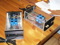
For your Dynaudios, if you really want to shake walls, a UCD400 or UCD700 would do nicely. With the UcD's you will find that you are able to turn up the volume without the sound becoming aggressive or tiring.
The support of Hypex is unsurpassed, and for a DIY newbie that you say you are, the build of such an amp would be easy.
This is how I built my monoblocks(see picture) : They deliver more than 100Watts into 8 Ohms, and are stable with an 8 Ohm load with 2 Uf in parrallel, which is a simulation of a Quad electrostatic speaker.
My current (and have been for a very long time) speakers are Klipsch La Scala, and yes, I realise they are very efficient, and that is why I chose an amp that is very quiet, has no problems delivering an open soundstage.
For your Dynaudios, if you really want to shake walls, a UCD400 or UCD700 would do nicely. With the UcD's you will find that you are able to turn up the volume without the sound becoming aggressive or tiring.
The support of Hypex is unsurpassed, and for a DIY newbie that you say you are, the build of such an amp would be easy.
This is how I built my monoblocks(see picture) : They deliver more than 100Watts into 8 Ohms, and are stable with an 8 Ohm load with 2 Uf in parrallel, which is a simulation of a Quad electrostatic speaker.
Attachments
janneman said:Yes and no. The concept is really not that complex. Normally you would feed the voltage across the emitter resistors of the output stage to a transistor base. That voltage is really a measure of the output transistor current Ie (Ie * Re = Vbe of the protection transistor). That transistor then starts to conduct if the current gets too high. You with me so far?
The protection transistor is connected to the driver stage, so when it starts to work it will steal drive current and thus limit the output current that will be available. So far so good.
The SOA implementation will take a resistor from the power supply voltage and use it to inject extra current into the protection transistor base. The protection transistor is connected with its emitter to the output, which is close to Ve of the output device. The output transistor Collector is normally connected to the power supply. So, the current injected by the extra resistor is really a measure of the output transistor Vce! (Injected current = Vce/Rinjection).
So, now the protection is activated not only by the output Ie but also the Vce. So, when Vce rises, smaller Ie will already trigger the protection because the protection transistor is 'helped' by the injected current which depends on Vce.
It is a little more involved because the SOA is not a nice linear combination of Ie and Vce, but that is the principle.
Jan Didden
Dear Mr. Didden,
thank you greatly for your extremely kind and valuable reply.
Unfortunately all this explanation is very well beyond my abilities of understanding.
Just a question: are you aware of commercial amps that employ this kind of very smart protection circuits?
Thank you very much indeed.
Kind regards,
beppe61
AndrewT said:Hi Beppe,
a simple fixed current limit will not protect the amp from failure and it will also limit too early. If you want I can explain this statement.
A VI limiter that comes close to the long term and short term SOAR curves and takes account of device temperature will protect the output stage from failure and it will not limit too early.
The VI limiter achieves the exact opposite of the fixed current limiter.
The design of a temperature compensated VI limiter that permits both long term limiting and allows short term peaks will be a technical achievement that many would want to copy. From past threads and other research I fear we are a long way from achieving this.
In the meantime you are relying on the designer compromising as best he sees fit to get the VI limiter as close as he wants to prevent warranty failures and only a few understand the complexity enough to avoid early limiting.
Listen and hope.
Thank you very much Mr. Andrews for the very interesting explanation.
In your opinion, all amps have some kind of current limiting devices/circuits or there are also amp without them?
They coudl be indeed a bottle-neck with demanding loads.
Of course output stages and power supplies must be built in order to be up to the task.
Kind regards,
beppe61
Dear Sir,
thank you very much again for your very kind and valuable reply.
Let me be more precise hereunder.
>
My sincere congratulations ! Great work indeed from all points of view.
Again dear Friend, I thank you very much for your very kind and valuable support.
I will report on my final solution.
Kind regards,
beppe61
thank you very much again for your very kind and valuable reply.
Let me be more precise hereunder.
>
Arty123 said:Dear Beppe 61, My current (and have been for a very long time) speakers are Klipsch La Scala, and yes, I realise they are very efficient, and that is why I chose an amp that is very quiet, has no problems delivering an open soundstage.
Actually the idea of changing speakers is another possible solution.
Dynaudio ask for powerful amps with an high damping factor.
If not the bass is weak, soft, slow and without control.
> For your Dynaudios, if you really want to shake walls, a UCD400 or UCD700 would do nicely.
After all my readings I think that at least a 400 is mandatory.
I would be very interested to hear from Dynaudio e UcD owners.
> With the UcD's you will find that you are able to turn up the volume without the sound becoming aggressive or tiring.
The support of Hypex is unsurpassed, and for a DIY newbie that you say you are, the build of such an amp would be easy.
Actually that is a fundamental point.
> This is how I built my monoblocks(see picture) : They deliver more than 100Watts into 8 Ohms, and are stable with an 8 Ohm load with 2 Uf in parrallel, which is a simulation of a Quad electrostatic speaker.
My sincere congratulations ! Great work indeed from all points of view.
Again dear Friend, I thank you very much for your very kind and valuable support.
I will report on my final solution.
Kind regards,
beppe61
janneman said:
It is a little more involved because the SOA is not a nice linear combination of Ie and Vce, but that is the principle.
Jan Didden
Hi Jan,
Well Said,
But if you look at SOA curves in case of Mosfets , they are much linear than BJT's in terms of Vds and Id combination....
Correct me if I were wrong...
K a n w a r
Workhorse said:
Hi Jan,
Well Said,
But if you look at SOA curves in case of Mosfets , they are much linear than BJT's in terms of Vds and Id combination....
Correct me if I were wrong...
K a n w a r
You are right, of course. Power FETS are not subject to secondary breakdown. This occurs in BJT as a result of high current with high Vce. That causes what is called "current hogging" where a small island on the die heats up more than another part, the hottest part will conduct more current, will become hotter, will conduct more etc. Because in effect only a very small part of the total chip or die will then conduct all the current, the allowed Pc gets much smaller. This current hogging occurs especially with higher Vce, so that is why the SOA shown much less allowed Pc at higher Vce then what you would expect from the DC Pc number.
Power FETs dont have this, so they can absorb higher powers at higher Vds compared with similar bipolars.
Jan Didden
What you say is true enough, BUT!
Second breakdown derates at around 10% /100C c.f. thermal derating of bipolars so your 250W TO-3 can well hold it's own against 150W TO247 MOSFETs for quality audiophile art. Maybe nothing in it.
In practice the MOSFET seems more rugged and forgiving of lack of SOA protection.
Cheers,
Greg
Second breakdown derates at around 10% /100C c.f. thermal derating of bipolars so your 250W TO-3 can well hold it's own against 150W TO247 MOSFETs for quality audiophile art. Maybe nothing in it.
In practice the MOSFET seems more rugged and forgiving of lack of SOA protection.
Cheers,
Greg
Hi Amp Guru,
10%/100C ?
Do you mean SOA falls by 10% when the temp rises by 100Cdeg?
That gives 90% at 125degC cf. 100% at 25degC.
I would think that power BJTs do a lot worse than this.
It is a bit difficult to compare because the manufacturer's data is generally on two different factors:- the Tc derating and the SOAR derating. Then you combine them for overall effect and resulting output maxima.
Can you explain or clarify?
amplifierguru said:What you say is true enough, BUT!
Second breakdown derates at around 10% /100C c.f. thermal derating of bipolars so your 250W TO-3 can well hold it's own against 150W TO247 MOSFETs for quality audiophile art. Maybe nothing in it. [snip]
Cheers,
Greg
No. The point is that because of the SOA limit, that 250W BJT can only dissipate say, 80 W at a Vce of 80V (1A max at 80V). Maybe you really should take a good look at a BJT power SOA curve at this point.
Jan Didden
janneman said:
You are right, of course. Power FETS are not subject to secondary breakdown. This occurs in BJT as a result of high current with high Vce. That causes what is called "current hogging" where a small island on the die heats up more than another part, the hottest part will conduct more current, will become hotter, will conduct more etc. Because in effect only a very small part of the total chip or die will then conduct all the current, the allowed Pc gets much smaller. This current hogging occurs especially with higher Vce, so that is why the SOA shown much less allowed Pc at higher Vce then what you would expect from the DC Pc number.
Power FETs dont have this, so they can absorb higher powers at higher Vds compared with similar bipolars.
Jan Didden
APT seem to have different idea about mosfet SOA and current hogging. Maybe i should have made separate topic on this...
http://www.advancedpower.com/TechSupport/ApplicationNotesSP/Downloads_GetFile.aspx?id=3855&fd=0
I just add as many pairs as possible.
Why not, if you are able to afford multiple transistors, (or got a bunch of samples ) parallel a bunch and have a really rugged output stage.
So in the bad case of a speaker connected with too low impedance, or the load gets reactive, you will be sure the amp will handle it.
Why not, if you are able to afford multiple transistors, (or got a bunch of samples
) parallel a bunch and have a really rugged output stage.So in the bad case of a speaker connected with too low impedance, or the load gets reactive, you will be sure the amp will handle it.
Hi Jan & everyone,
In Traditional Output Device Protections designer usually consider mainly 2 parameters Vds & Ids across the output device and than implement a SOA protection...which is though a very good in case of Reactive Loads & Resistive Loads.....
But when a Pure Resistive Short Circuit is encountered, the SOA limiter Still limits the output but the Protection always goes on cycling again & again whenever the threshold of over-current detection is crossed or reached but this still leaves some finite output current which is always greater than Idle current through the output device in No signal conditions and thus results in temperature rise.....if not dealt with some means through which one could make a Difference between an Over-Current & Short-Circuit...
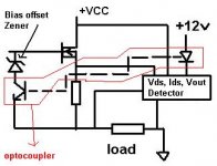
I have a rather simple concept in my mind which uses Three Parameters Vds, Ids , Vout to detect the Status of Device health and upon some bad load limits the Gate drive of output Mosfet....
In case of Short-circuit.....The Idss rises very abruptly and at the same time Vout equals to Zero or tends to zero....If this condition is considered well enough than the circuit could be made to limit the gate drive of mosfet at once and there would be no need of cycling of Idss to trigger again & again the overcurrent threshold... because we have the Third key parameter Vout which is there to tell that there is no output and limit could be engaged indefinately untill the short circuit is removed and hence no dissipation of output results.....
Attached is a simple block circuit
Lets consider Short circuit
In case of normal operation the Vout would be always present & optocoupler would be OFF hence no limit
In case of Short Circuit ..The Vout tends to Zero and optocoupler gets ON and limits the Gatedrive....hence Ids is limited to idling current due to the bias offset Zener....[the value of Vz zener is choosen to offset the bias voltage upto 4 volts]
Waiting to hear any helpful suggestions regarding Pros-Cons of this idea....
K a n w a r
In Traditional Output Device Protections designer usually consider mainly 2 parameters Vds & Ids across the output device and than implement a SOA protection...which is though a very good in case of Reactive Loads & Resistive Loads.....
But when a Pure Resistive Short Circuit is encountered, the SOA limiter Still limits the output but the Protection always goes on cycling again & again whenever the threshold of over-current detection is crossed or reached but this still leaves some finite output current which is always greater than Idle current through the output device in No signal conditions and thus results in temperature rise.....if not dealt with some means through which one could make a Difference between an Over-Current & Short-Circuit...
I have a rather simple concept in my mind which uses Three Parameters Vds, Ids , Vout to detect the Status of Device health and upon some bad load limits the Gate drive of output Mosfet....
In case of Short-circuit.....The Idss rises very abruptly and at the same time Vout equals to Zero or tends to zero....If this condition is considered well enough than the circuit could be made to limit the gate drive of mosfet at once and there would be no need of cycling of Idss to trigger again & again the overcurrent threshold... because we have the Third key parameter Vout which is there to tell that there is no output and limit could be engaged indefinately untill the short circuit is removed and hence no dissipation of output results.....
Attached is a simple block circuit
Lets consider Short circuit
In case of normal operation the Vout would be always present & optocoupler would be OFF hence no limit
In case of Short Circuit ..The Vout tends to Zero and optocoupler gets ON and limits the Gatedrive....hence Ids is limited to idling current due to the bias offset Zener....[the value of Vz zener is choosen to offset the bias voltage upto 4 volts]
Waiting to hear any helpful suggestions regarding Pros-Cons of this idea....
K a n w a r
Attachments


- Status
- This old topic is closed. If you want to reopen this topic, contact a moderator using the "Report Post" button.
- Home
- Amplifiers
- Solid State
- Does any power amp have a current limiting device?