Hello Prasi,
Please have a look here
Mouser Electronics, Inc. Romania
I have doubled all parts number (so it is for stereo amp), and also put 6 MOSFETS instead of 4, just to be sure if 2 go up in smoke or destroyed other way..
Regards,
Daniel
Hello Daniel,
the bom looks good to me.
only 2 changes...
1. instead of 660-MF1/2LCT52R102J , I suggest you to replace it with this 603-MF0207FTE52-1K .
2. instead of 534-4527 and 534-4527C, replace with 534-4628 and 534-4628C
All the best for your build.
regards
Prasi
cool project.. I will give a try.
Hello bruno,
The PCBs shipped to you were returned to me, with a canadian post sticker saying "Reason: Unclaimed".
Please let me know if you are still interested in the project.
regards
Prasi
Hi good people. I finally registered this great place where I have already found alot of good info during years.
I am on the lookout for a circa 2watt highquality amplifier to do tweeterduty for my Dali 18 mk2 speakers that im driving actively.
My question is weather i can just use a lower voltage PSU for the DLH, and this way get lower output and idle consumption while maintaining its soundquality. Best regards Allan Kvist Denmark
Assuming a load of 8 ohms, I would suggest starting with a minimum rail voltage of 11.41 V (taking into account the ripple) and a bias of 0.71 A. This supposes a dissipation of 8.1 W per rail. The bias would enable the two modes of operation of the output (SE and PP), to obtain up to 2 W.
Also, check if the THD levels under that current are still acceptable.
Best regards
Also, check if the THD levels under that current are still acceptable.
Best regards
Diegomj1973 Wonderfull. Thank you for giving the answer I was hoping for 😉 Im sure I will give it a try as soon I have done a ton of things that my sweet wife finds more important. At the moment I have a 70 watt class AB driving tweeters. Will be a nice day when I sell this for more money than the dhl should cost to build if i salvage a few parts☺
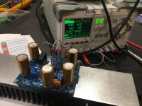
Exactly what i am planning to do with mine Guerilla. They will be the tweeter amps for a fully active system. I have the very nice Prasi boards - all too easy to click on the link to the project at PCBway, pay the ~$20 and have them arrive within a week. Photo of mine gently roasting on my lab PSU at 15V/~1A. Sink only mildly warm (34C).
Attachments
Thanks Prasi, I will play around with bypass caps for sure - I have some premium "audiophile" caps I salvaged from elsewhere that might work well. Although it only took just over a week to go from ordering PCBs to having them powered today, it may take a while longer to get to point of listening...the rest of system is in pieces at present  . Will let you know though...
I'm stuffing some of the CRC boards I bought from your GB to use to power these at least initially. I have just ordered some of your CapMu boards from your PCBway site that might get used eventually - I really commend you to keep loading your designs there. Although it is easy to load up gerbers to these production sites, having a library of reliable design data accessible, essentially with one click, takes it to another level (although possibly a bit too addictive).
. Will let you know though...I'm stuffing some of the CRC boards I bought from your GB to use to power these at least initially. I have just ordered some of your CapMu boards from your PCBway site that might get used eventually - I really commend you to keep loading your designs there. Although it is easy to load up gerbers to these production sites, having a library of reliable design data accessible, essentially with one click, takes it to another level (although possibly a bit too addictive).
Hello bruno,
The PCBs shipped to you were returned to me, with a canadian post sticker saying "Reason: Unclaimed".
Please let me know if you are still interested in the project.
regards
Prasi
If anyone would like to have a pair of PCB's , let me know. I have a pair.
USD 8 all inclusive.
regards
Prasi
Last edited:
can I use for the upper pot (key S) a 500ohm pot?VIRTUAL EVALUATION OF SCHEMATICS
<snip>
will this decrease performance?
If anyone would like to have a pair of PCB's , let me know. I have a pair.
USD 8 all inclusive.
regards
Prasi
That is a very good price! I ended up paying for a pair $17CAD with shipping. After it was offered for...........
Someone should grab those
Greetings
Hi Guerilla,
Yes you could definitely order from the site and link is valid.
Here is the post # 359 containing the order link.
DLH Amplifier: The trilogy with PLH and JLH amps
regards
Prasi
Yes you could definitely order from the site and link is valid.
Here is the post # 359 containing the order link.
DLH Amplifier: The trilogy with PLH and JLH amps
regards
Prasi
Last edited:
can I use for the upper pot (key S) a 500ohm pot?
will this decrease performance?
The ratio of values between the upper trimpot and the lower trimpot ranges from almost 3 to almost 7 times, depending mainly on the parameters of the mosfets. (2.9175 to 6.835, according to theoretical calculations).
If the upper trimpot takes values of 500 ohms, the dissipation of the bjts will grow to a risky value and there will be a large shift of offset with the temperature. The collector current could reach excessive values between 23.3 mA and 27.3 mA.
It is necessary to maintain the collector current around a value close between 10 mA and 12,5 mA.
Best regards
Last edited:
Single supply details?
Hello all. I’ve been looking for this type of amp for awhile now. I want to thank all those who have contributed to the evolution of this wonderful design.
Like several others are doing, this will be an amp in my bi-amp system and it will be driving very efficient horns. I have concerns about DC offset and so I’m considering using an output coupling cap which will serve as a DC block/high pass filter to help protect the compression drivers. So I was happy to see a single supply, cap coupled design in post 357. Thank you DiegoMJ for posting this design. I didn’t see a PWB design for this (although I could have missed it). If not, can Prasi’s artwork on PCBway be used to build it up? Xrk, it sounds like you build one of these, any advise?
Also, along the power supply line, Xrk, in post 201 you describe various different filter stages you use. Are there posts somewhere that describe this in more detail? I’d be interested in hearing more about them.
- Home
- Amplifiers
- Solid State
- DLH Amplifier: The trilogy with PLH and JLH amps