Qusp, your positive contributions are always appreciated.
I can see that diyinhk has replicated the layout recommendation in p.6 of the same document you quoted. There the input signal also crosses the "massive" power lines at a right angle.
Perhaps what you are proposing is an optimization to what ESS is recommending?
Do I not read the recommended layout from ESS right?
Do I not read the recommended layout from ESS right?
yes thats the problem, something I think Diyinhk did as well, though the many instructions to avoid splitting the ground plane/return should have been a hint
I can see that diyinhk has replicated the layout recommendation in p.6 of the same document you quoted. There the input signal also crosses the "massive" power lines at a right angle.
no he doesnt, in the app note the IV resistor is first before the split and the rails are on the top side and are solid planes split by that line, not thick traces splitting the ground plane on that line, only the feedback paths cross the gap in the power planes and given the feedback the error should be somewhat mitigated. but yes I would take this further, given the regulators arent on the board anyway. there is no need for the inputs to disturb the ground plane at all under any circumstance.
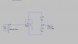
Output Section
The output section expanded in Figure 6 shows the opamps, filters, and XLR and RCA connectors.
Figure
6 shows one of the eight identical output stages on the evaluation board. The top copper layer of the PCB is shown in red, the bottom is shown in dark blue and notes for the purpose of this document are in green.
The +12V and -12V split planes are shown separated by the coral colored lines. The +12V and -12V split planes provides solid connections (circled in green) to the power supply for the outputs. Ensure that the
connection to the rest of the plane is solid and not cut off on an island due to other traces being routed on the top layer.
Last edited:
Is there a practical difference between crossing the power lines with a trace or with a resistor?. I do notice the resistors are before the power lines, but you still have to cross the power lines with a trace. (and if so could you link to a reference?)
I've taken a closer look at the actual implementation of what is recommended in the ESS documents, ie, the evaluation boards that can be purchased from the distributors (I don't have one, but have pictures)
There the power lines are not in the top, so must be in the bottom. The top ground fill is also split along the middle of the opamps. The layout recommendations in the document shows the power lines running under the opamps.
If you have a photo of the bottom of the evaluation board, could you forward the link?
But your suggestion about ground is welcomed.
Suggestion for next versions: have left and right power input so as to allow a wide center uninterrupted ground plane in the middle of the board. (In other words break the power lines in the middle so as to have right and left power lines)
I've also traced the signal lines from DAC to opamp on the bottom side of the board and the return under the signal lines is pretty clean from the power lines to the DAC.
What pins are the signal return paths in the opamp?
there are no power lines, there are power planes, the coral lines are splits/edges of power planes and they talk about not sharing ground vias, if the ground plane was on the top there would be power vias, not ground vias.
the only trace that splits the top is AVCC, a completely quiet and constant AVCC/2, but the ground is solid under it except for a couple of short lengths of feedback trace which dont block the return.
but look its not my job to fix a manufacturers layout, neither is it yours.
the only trace that splits the top is AVCC, a completely quiet and constant AVCC/2, but the ground is solid under it except for a couple of short lengths of feedback trace which dont block the return.
but look its not my job to fix a manufacturers layout, neither is it yours.
the ground plane may be divided underneath the DAC as shown. The top side is kept clear from traces to provide a solid AVCC connection on the flooded plane.
Last edited:
there are no power lines, there are power planes, the coral lines are splits/edges of power planes and they talk about not sharing ground vias, if the ground plane was on the top there would be power vias, not ground vias.
but look its not my job to fix a manufacturers layout, neither is it yours.
I took a look at the top and bottom artwork in the ESS docs. The power lines are not there. So likely it is a 4-layer board.
In any case, the bottom layer (GND) is clear in between the opmaps, so splitting the power lines into left and right is a good suggestion (I think).
This is a diy board. Many manufacturers have benefited from the input of people here. I have no problem sharing my ideas...
ive not ever seen the board in the flesh and they arent explicit in the document.
it doesnt have to be a 4 layer board though and I actually doubt it is. I didnt suggest they are on the bottom. the top is sectioned into power planes and the trace you think is splitting the top plane, is rather just travelling in the gap between the positive and negative power planes.
if its a 4 layer board they havent made very good use of it, there would be no need to have the signal jump between layers for the feedback path if they had 4 layers. nah look at figure 7, its 2 layers; there is no way they would laid it out like that with 4 layers. btw the X's are net points, they stand for output/input pins, power connections, layer changes and ground vias.
*its possible its 4 layers I guess nothing rules it out, but that just takes me to my next point
on top of this, I think weve been working with the ess long enough to offer some improvements on the 9008 eval board dont you?
at this point glt, i'm helping you, not the manufacturer, despite not getting a great deal of encouragement. I get frustrated, I let that show, its taken me what 3 weeks to try and get this point through?
Last edited:
...
at this point glt, i'm helping you, not the manufacturer, despite not getting a great deal of encouragement. I get frustrated, I let that show, its taken me what 3 weeks to try and get this point through?
I certainly hope you are enjoying this. You are one of the most prolific posters...
It has taken this long because not everyone (or even hardly anyone) is at your level...
I certainly hope you are enjoying this
not really, I just dont like a job unfinished
")
which it seems to be, plenty of other stuff, but those are the major ones and I dont have the energy. i'm dwarfed by those that surround me, standing on the shoulders of giants I believe. I have a LOT to learn.
whats that saying?
The more I learn, the more I realize I don’t know. The more I realize I don’t know, the more I want to learn.
– Albert Einstein
good luck.
Last edited:
whats that saying?
The more I learn, the more I realize I don’t know. The more I realize I don’t know, the more I want to learn.
– Albert Einstein
Ἓν οἶδα ὅτι ουδὲν οἶδα [= I know one thing: that I know nothing]
Socrates
and ignorance is bliss eh ?
"Knowledge puffs up but love builds up" St. Paul.
Group hug people ?

And all of this, dear friends, is why it is actually best to buy a pcb designed by someone who knows what they're doing rather than just the cheapest pcb that takes the DAC chip that you think you want. The datasheet pcb design is the minimum standard to achieve IMO. I know I am flogging a dead horse here, but, why exactly did qusp need to explain all that is wrong with a flawed product? Why did he need to spend HOURS writing all of that stuff that is nothing more than repeating publicly available information on the DAC implementation and basic PCB design principles? As he's admitted there is still plenty to PCB design improvements that are left to implement after the changes he has suggested. He is mostly concerned with maintaining a minimum standard for DIY audio pcb design, there is still plenty of room for improvements past this and still there is very little savings by having built (and compromised) a lot of expensive parts onto a cheap PCB. I just do not understand the logic here.
Last edited:
And all of this, dear friends, is why it is actually best to buy a pcb designed by someone who knows what they're doing rather than just the cheapest pcb that takes the DAC chip that you think you want. The datasheet pcb design is the minimum standard to achieve IMO. I know I am flogging a dead horse here, but, why exactly did qusp need to explain all that is wrong with a flawed product? Why did he need to spend HOURS writing all of that stuff that is nothing more than repeating publicly available information on the DAC implementation and basic PCB design principles? As he's admitted there is still plenty to PCB design improvements that are left to implement after the changes he has suggested.

Again, you're just having a rant. Anyone would think Brisbane is a horrible place to live the way you go on. What's the excuse this time ? Got a hangover ?
no, maybe just a healthier dose of realism in the sunshine over here? i'll tell you whats getting boring, the lame 'must be drunk' 'must have a hangover' defensive cheap shots you keep spouting.
honestly I dont know how the design can be defended, it showed a fundamental misunderstanding of fairly basic design and electronics principles. It went against nearly all the recommendations in the document the schematic copied from (the document from another dac...) not because he thought he knew better, rather just didnt know.... which leads one to believe it was not understood.
just about all those quotes about the ground plane, those are all on one page, the page with the recommended layout on it.
this stuff should be taken care of on prototype PCBs, the customer and onlookers should not be paying for such elementary mistakes.
just about the only participation I have seen from the OP has been promoting his designs here, right down to the user name chosen. I guess I just dont like seeing members here paying for companies R&D in money and time.
Last edited:
Notwithstanding the strong desire to see this product fail, I am not throwing mine away and may buy more in the future. For $99 bucks it is great product. As I said before, no one is claiming that this product will surpass Acko and Buffalo and no one is expecting that either. But is has the right to exist and some people (like me) wishes it to improve.
On top of that, it is a great board for diy and to learn. For example, I learned about capacitors sizes and their effect on bypass.
All the argument about its flaws made me study the ess layout artwork to understand more about grounding and power.
etc...
In the meantime, I overlayed the art work found in the ESS docs. This is what I understand:
The power planes are on the top plane: one half is one polarity, the other half is the other polarity. All the signal components for the opamps are laid out in the middle and completely surrounded by the power planes. If it is not good to cross a power line, then it is probably not good to be running along power planes.
The ground plane is in the bottom. It is interrupted by the traces around and under the opamps and completely open and clear in the areas outside of the opamps. So it is not fully solid.
no, you are incorrect. the top is segmented power as you suggest (and as I said), but the traces for signal travel part way along the top surrounded by solid power plane (which actually isnt a problem) but are all the while having ground plane underneath them. then they travel for a short length to the IV resistor and filter, then back down to the bottom as part of the opamp feedback loop 15-20mm, which is surrounded completely by ground plane and does not block any (line of sight) return path back to the dac. The rest is on top
the blue traces are the only ones on the bottom in the ground plane.. there is no middle layer
and in answer to your earlier question, return currents where do they come from? the opamp power supply rails, the dac itself and ground. In most circuits the decoupling caps are part of the signal current loop. that is how you can have designs like this cute novelty posted by shinja here
I dont know how many times I must repeat this, the signal lines should traverse an unbroken ground plane where possible. the return currents should be able to traverse a line of sight return back to the dac. that is what they have done, there is nothing blocking that, there is little on the bottom at all, but nothing blocking that. Compared to almost the entire width being cut twice from one side to the other, I think we can forgive that given the 2 layer PCB.
its a 2 layer PCB, of that i'm 99% certain. check out the 2 channel 9018 eval board posted in the thread on the first page at the moment. its almost identical to the 8 channel layout and you can see planes on top with a good number of signal traces too.
you mistake my wanting the design to be more than a prototype before going on sale, ignoring or dismissing real problems with the design, with wanting it to fail. $99 or not, besides it keeps growing and once you add everything to complete it....
Attachments
Last edited:
...
I dont know how many times I must repeat this, the signal lines should traverse an unbroken ground plane where possible. ....
But the lines ARE traversing the power planes. The connecting line under the board traverses the +V to the -V (or - to +) which are on top of the board. In this board the signal line which is on the top, traverses the power lines which are on the bottom.
I would say that the ESS layout is pretty clever: rather than ground fill, it is power plane fill. Haven't seen that before, and it allows for a two layer board.
I have seen people reviewing the eval board connected to switching supplies (which in the eval board the power planes surround everything) and the results are good.
Last edited:
record on repeat. there are no specific return currents to worry about blocking here and the traces are completely surrounded by ground plane and it is after the IV resistor.
glt, its clear you dont understand the circuit either, or what the problem is with it.
i'm out, enjoy!
glt, its clear you dont understand the circuit either, or what the problem is with it.
i'm out, enjoy!
Last edited:
...
glt, its clear you dont understand the circuit either, or what the problem is with it.
...
I certainly don't buy that.
- Home
- Vendor's Bazaar
- diyinhk Store