This is as nice, straight forward and helpful an explanation as I have seen. Answers like this encourage Newbies to continue to ask questions and LEARN as they create great products.
Thanks for the kind words - I have had so much fun and satisfaction with making my own audio gear that I want to help anybody interested with making their own.

Many thanks for this guide and for all the followup!
I'm preparing my first F5 build and would have been totally lost without this.
Just for my understanding: I'm using the diy audio v3 PSU, the entire construction of the rectifier section looks rather fiddly to me and -stupid as it sounds- I have great trouble locating appropriate heatsinks. From what I gather, if I want to go without the sinks I'd either have to go for TO-247 and mount them under the board, directly on the 'floor plate' of the chassis, using Keratherm.
Or use a 'prepackaged' full wave bridge such as shown in one of the pictures. If I go for the prepackaged one, I can just omit the entire diode section of the board, right? I know next to nothing of these things but am slowly studying 'The art of electronics' and table 6.4 mentions a MDA3500-10 full wave bridge that has a drop of .85V and can handle 35 amps. Problem is, I can't find it online but I did find this:
Diotec B 40/35 - 25 Silicon Bridge Rectifier 25A Nominal current 25 A (requires heat sink) U(FM) <1.2 V U(RRM) 100 V from Conrad Electronic UK
It's rated to handle what I assume is a continuous voltage of 40Vrms and 25 A. Can anyone confirm that one of these/channel will work with my 500 VAC (2x18V secondaries) transfo if I just mount it on the floor plate (which will double as a heat sink)?
Many thanks for your insights and apologies, it's probably a stupid question but I know next to nothing of these things.
You have probably found the answer already, but yes, that mono-bridge from Conrad should work ok, mounted to case for heatsinking (with a dab of thermal compound to aid heat transfer). Although I would choose the model with higher voltage rating (Diotec B 250/220 - 25), to give a better safety margin, since they are almost the same price. You need two of them for a transformer with dual secondaries (2x18v).
I have the Universal Power Supply from DIYaudio store for the F-5 v3.0.
I want to use much more capacitance, so instead of eight 15 000uf 25V caps, I got eight 70 000uf 50V caps. Went a little crazy here.
Do I need to do any further changes to the first watt power supply design when using more capacitance (0.56F)? More resistors, or more durable 0.47 ohm 25W resistors with metal chassi?
Last edited:
You have 70,000uF 50V caps that fit that PCB??
You'll need a bigger mains fuse.
Nothing else really changes in the PSU... other than your inrush current on power-up will be immense.
You may seriously want to consider using 4 of the caps. It's still much bigger than stock.
You'll need a bigger mains fuse.
Nothing else really changes in the PSU... other than your inrush current on power-up will be immense.
You may seriously want to consider using 4 of the caps. It's still much bigger than stock.
Rewind, you're going to need at least 140 milliohms of DC resistance in the secondary circuit. Otherwise the first sinewave half-cycle of AC mains power will give you an inrush current that exceeds your diode bridge's spec of 300 amperes "Peak forward surge current". Please tell us that your DID look up your bridge rectifier's specification for peak forward current, and that its datasheet DOES say 300 amperes or more. Please don't tell us you can't be bothered with such numbers and data and left-brain rational thinking. Please?
You will need to measure your transformer secondary's DC resistance with an accurate (not a cheapo Harbor Freight multimeter!) instrument. If it's less than 0.14 ohms, add enough #16 AWG wire in series (at 0.0004 ohms/foot), between secondary and bridge rectifier, to boost the series combination up to 0.14 ohms or greater. If you simply cannot stand to make a resistor out of #16 wire, buy a 25W chassis mount resistor of the appropriate resistance (or higher!) Such As This 25W Resistor
Why 140 milliohms? Because calculus tells us so. If you are skeptical, other DIYA readers/posters will be only too glad to type the I=CdV/dt equation and show you how to plug in the numerical values for your specific situation. (In my opinion it is unwise to doubt the 140 milliohm number -- but you are not me -- do as you like)
If it presents problems, I could use half of them (4 x 70 000uf/50V) and stick to the original design with a larger fuse. They use screws, but I could hand wire this part.
I am using the Antec AS-4218 18v+18V 400VA transformer. I don't have the tools to measure low ohms, sry. Here is more info on the transformer:
http://cdn2.bigcommerce.com/server6...6/AS_4218__09756.1409694264.1280.1280.jpg?c=2
I have not decided yet on bridge rectifiers. Thank you, Mark J, I will take your advice.
"kortvarig" used another software called Microcap to do some nice sims in post #77:
Halair FirstWatt F5 byggetråd - Side 4
Non-scandinavians can use Google Translate from Norwegian to English.
"With CLC part 20mH and 1x30000uF on each side of the coil, there is virtually no visible ripple. Signal modulation was also less than about 16mV pp.
Only 1.8mH as in the diagram, shown not long ago, gives visible ripple of about 144mV pp with sinus form, and signal modulation is approximately 16mV pp.
Although I once have discarded CLC part because of a "Boogie Woogie sound", think I'll try again for my last and ultimate class A amp. The problem is getting into 20mH with minimum resistance.
One should also be aware of what happens when the amplifier starts up, it takes some time before it all fell into place with 20mH. It does not seem to be something dramatic happens."
Last edited:
Or maybe this one: Jantzen Air Core Coil 20mH AWG17 2,55Ohm, 000-1718 - Fidelity Components Shop
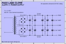
I found this CLC schematic. This is probably the one they are discussing in the Norwegian site, but instead with 30 000uf on each side of a 20mH inductor.
I found this CLC schematic. This is probably the one they are discussing in the Norwegian site, but instead with 30 000uf on each side of a 20mH inductor.
Attachments
Last edited:
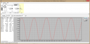
Attempts at simulating a CLC PSU:
I have never used PSU designer II before, but here we go.
Uknown parameters:
¤ The resistance of 18 + 18V 400VA Antec trafo. I found one example where a 30V trafo had 100 milliohm resistance.
¤ The resistance of the caps. I found one example stating that 15 000uf caps have 5 milliohm.
Other facts:
20mH was difficult to find with low enough resistance.
The resistance of the 4,7mH/0,6 ohm/350W Jantzen foil inductor is known. This is the largest air coil with copper foil I found at partsexpress.com. Foil has much lower resistance than regular inductors between 0,48-0,6 ohm, but is it low enough not to produce heat? They handle 350W so it should be enough.
I chose a 1N4003 as bridge rectifier (30A/200V). Mark J suggested more than 30A for larger capacitor banks but, the PSU designer II simulation was not affected much by this choice. Something to consider later.
¤ I hope I am correct in assuming that the F-5 has a 1.3A load on the PSU.
Some of the inductors in the sims:
4,7mH/0,6 ohm/350W Jantzen foil inductor: Jantzen Audio 4.7mH 14 AWG Copper Foil Inductor Crossover Coil
1,8mH/0,48 ohm Jantzen foil inductor: Jantzen Audio 1.8mH 16 AWG Copper Foil Inductor Crossover Coil
A thought from all this is that the roundness of the curve is sensitive to the resistance of the capacitor. I don't know the resistance of the capacitors, as this is not written on the cap. So I am left guessing, and this affects the simulations a great deal.
Attachments
Last edited:
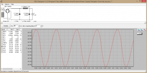
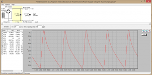
Attempts at simulating a CRC PSU:
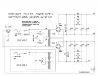
I give you the original Nelson Pass CRC power supply from the F-5.
You decide if it is correct. I did my best, but I am bioengineer, dammit, not an electrical engineer.
I added the 0,1175 ohm resistor because: Req= (1/0,47+1/0,47+1/0,47+1/0,47 )^-1= 1/8,51 ohm = 0,1175 ohm
Hope that is correct.
Papa's CRC PSU is pretty jagged. I guess that is why CLC is preferred.
Attachments
Last edited:
The 1N4003 is not a good choice of diode for that supply, not even in simulation. Compare its datasheet "max average current" spec against the simulated load of 1.3 amperes: oops!
I suggest you simulate using 35A, 1000V diode bridge rectifier in the GBPC package (like this one). There is a SPICE .MODEL for it on the Cordell Audio website.
I suggest you simulate using 35A, 1000V diode bridge rectifier in the GBPC package (like this one). There is a SPICE .MODEL for it on the Cordell Audio website.
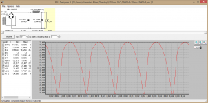
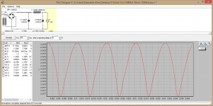
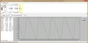
CRC:
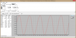
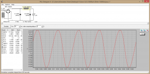
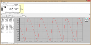
I simulated the wrong cap for the original F-5 PSU. Here is how it looks like after the second caps, on two different bridge rectifiers. Still pretty ugly graphs. Would be fun to do the CLC.
Mark Johnson: I found a stronger rectifier for you in the red graph. This one: BY329-1000 Datasheet - Philips Semiconductors | DatasheetLib.com
I see no difference between 1N4003 and BY329 in this particular graph.
Attachments
Last edited:
- Home
- Amplifiers
- Power Supplies
- diyAudio Power Supply Circuit Board v3 illustrated build guide