Hi Freecrowder,
Yes, the input capacitor will block the DC from the preamplifier. However, I would call the preamplifier broken. Get it fixed before using it. OTherwise it can generate noise when changing volume rapidly or changing inputs or going in and out of mute.
If it is a tube based preamplifier, you especially need to have it fixed. Tube preamps should have zero (0) volts out under any condition. Any voltage out means the coupling capacitor is leaky. That probably goes for other ones inside the preamplifier and that can burn out tubes.
As for the input impedance, I would have to look at the diagram to tell you, but it will be the value of the resistor in parallel with any resistance on the other side of the capacitor and the input devices if they are low impedance.
-Chris
I think you will be best using a 45vac x2 transformer, regardless of impedance you will use it at, make it work correctly for all outputs.
Also the bigger difference the output versus rail voltage the better it will sound.
I used a 45vac teriodal with no problems power wise. Higher voltage is better in my opinion.
600va per channel is good also
Also the bigger difference the output versus rail voltage the better it will sound.
I used a 45vac teriodal with no problems power wise. Higher voltage is better in my opinion.
600va per channel is good also
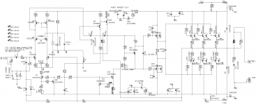
Hey, I have also tried to draw the schematic of the honey badger based on the schematic picture given in the build guide. Based on my drawn schematic I have layouted a pcb and milled it. Now I have soldered everything and R50 gets very hot immediately.
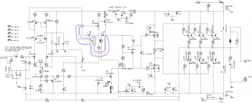
I have found Prasis' schematic of the honey badger. I think it is similar to mine, but his have one more electrical line (I attached his schematic and marked this new line in blue). I hope somebody (or Prasi himself) can help me. Regards Oliver
I have found Prasis' schematic of the honey badger. I think it is similar to mine, but his have one more electrical line (I attached his schematic and marked this new line in blue). I hope somebody (or Prasi himself) can help me. Regards Oliver
Attachments
Hey,
thanks for your reply.
For Q1 / Q2 I am using 2 MPSA42 (as mentioned in the build guide)
For Q5 / Q6 I am using 2 KSA992 (as mentioned in the build guide)
For the miller capacitances (C7 / C8) I also took the values from the build guide.
It is not only the that R50 is hot (to describe it exactly: after 15 seconds R50 is way too hot to touch it...) .
Also I have replaced the fuses by 10Ohm resistors as it is adviced in the build guide. The I measured the Voltage drop over such a resistor. In the build guide it is mentioned that something close to 0V should be displayed. My DMM showed something like 4,5V.
Regards Oliver
The oscillator is using that 4.5v. Be suspect of your sourcing , are all transistors genuine ?? The design is broadly derated , 99% of Badger builders are "floored" by the performance. So , some unfortunate misfortune befalls you. Show some voltage readings. This amp is in my head .
OS
OS
level shifters and the VAS driver may be phase shifting the signal enough to produce oscillations. try bypassing the driver 1845/992 with a 100 ohm resistor where the base / emitter pins go.
I built this without Q3/Q4 and Q9 and used led for constant current selection. SX-780 and SX3700 use a very similar topology
Works really well
I built this without Q3/Q4 and Q9 and used led for constant current selection. SX-780 and SX3700 use a very similar topology
Works really well
Last edited:
Good evening,
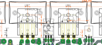
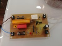
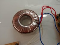
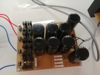
at first: attached you may find a few photos of my setup. I am using Soft Start from DIY-Store (PCB is selfmade that is why it looks different), an toroid transformer rated with 45V - 45V and 400VA, the universal PSU from DIY-Store (PCB is selfmade that is why it looks different), and the honeybadger (PCB is selfmade that is why it looks different). I double and tripple checked close to everything very carefully. I am sure that I didn't make a mistake during layouting and soldering. I also checked of course the E C B positions of each transistor and if it is connected correctly to the board. There is also no short between the transistors to the heatsink (plastic washers and insulating tape is used... and I also measured it)
The PSU gives an output of 129,6V from positive to negative rail (64,8V from negative to ground; 64,8V from positive to ground) if the amplifier is not connected. If the amplifier is connected the PSU gives an output of 125,5V from positive to negative rail (62,8V from negative to ground; 62,8V from positive to ground).
I have measured the voltage between the Bases of Q3/Q4 and the ground: about 13,7V
Voltagedrop over the fuses which are bridged with 10Ohm resistors: 3,2V for F1 and 3,2V for F2
The problem is still the same. R50 gets way to hot after 10 to 15 seconds. There are no other components which get hot. Both LED's are shining normal.
Ostripper: You asked for voltage measurings. From where to where should I measure? All transitors are from "Reichelt". A very big german electronic distributor. You mentioned a too high gain class for Q1/Q2 (I am using MPSA42) and Q5/Q6 (I am using KSA992). Can you give me an advise what else to use?
Kay Pirinha and Ostripper: Both of you state that my problem is oscillation. By what is this oscillation caused and how can I eliminate this?
Best Regards,
Oliver
Attachments
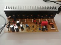
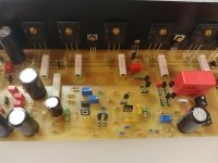
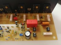
First of all , that is not a official HB PCB.
I see you have a ground plane between traces , is it grounded? Ground planes are good for RF. Could be either good or bad for a audio power amp.
Sockets for the small signal devices could be a issue (if one dislodged). mpsa42/92 will technically work .... but - they are EBC , badger tranny's are BCE. But I don't have your layout ??? Too many variables here.
Edit - many extra pF's of stray capacitances here. But , very nice work.
Edit 2 - possible inductive feedback from power sections to small signal sections. The sectioning and empty spaces on the official PCB have purpose.
OS
Last edited:
Hey,
you are right, ostripper. It is not the official HB PCB. I have used exactly the schematic of post #1970 (without the marked blue electrical line) which is also the schematic which is shown in the offical HB build guide. I made the schematic and afterwards the layout with the programm "KiCAD". That means it is not possible to create wrong electrical connections between the components during layouting (as long as the schematic is correct). All my components are named exactly like in the schematic which is in the build guide. So if you would say measure the voltage between Base of Q3/Q4 and ground I can exactly do this and there wont be any missunderstandings.
I know that MPSA42 are EBC and I take it into account while creating the layout.
I think I can be pretty sure that I didn't make a mistake while soldering (I checked everything so many times in different ways).
Because of the sockets for the signal devices you are maybe right. I will solder them directly to the PCB.
I think it would help me if you can give me an advise where to measure voltages.
Maybe you can also comment the voltage-measurements I have done in Post #1976.
On top of that: By what is this oscillation possibly caused and how can I eliminate this?
Regards,
Oliver
Last edited:
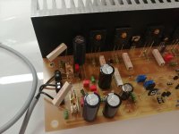
If I get it right, you've arranged the output and input terminals quite close to each other at the PCB's bottom right corner, as shown in the pics. In addition, the output inductor comes close to the input coupling capacitor. Maybe the few pF's between these components are enough to turn a high bandwith amplifier like the HB into a power oscillator.
Best regards!
Best regards!
- Home
- Amplifiers
- Solid State
- diyAB Amp - The "Honey Badger"