I measured a wide variety of transformers and had to take the high factor to assure the longevity of the 63v caps.Daniel, I don't know where your x 1.45 multiplier comes from?
And, problematically, it is most likely for someone to use a higher voltage transformer anyway, so that problem takes additional derating. So, I "started the bargaining" at 35-0-35 (imagine auctioneer), while hoping to end up no more than 36-0-36 (if when 63v caps are used in the supply).
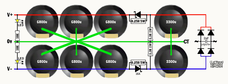
CRC filter supply for use with a high power amplifier that has a wide range of current. The resistor is for use during low/normal volume playback and the diode is for use during maximum power loud playback.Why do you include a diode and paralleled resistor in each rail?
The voltage loss of my power supply crc filter is diode limited to 0.3v, because low loss is quite attractive and because Honey Badger already has crc filtering at small signal.
A good question would be, if the 0.25R was reduced to 0.125R (without the bypass diode) then how much more capacitance need be added to maintain the same crc filter effectiveness? That probably wouldn't be an inexpensive compact supply; however, it would be an interesting comparison.
Only one: "BassHeads" who favor a "push for power" build, will like a dual secondaries transformer driving a pair of bridge rectifiers (8 diodes total), because more effective transformer utilization directly relates to more powerful bass dynamic impact.. . . as few diodes as possible to perform the necessary rectification. . . Did I miss anything?
Last edited:
Well your answer would have to be based on how you define the quality of a PSU. My main interest is that if you have a tried-and-true solution that satisfies you in practice, it would be a useful datapoint.
only that i make my traffos larger than commercial offerings since i make them myself....
CRC filter supply for use with a high power amplifier that has a wide range of current. The resistor is for use during low/normal volume playback and the diode is for use during maximum power loud playback.
The loss of my power supply crc filter is diode limited to 0.3v, because low loss is quite attractive and because Honey Badger already has crc filtering at small signal.
It might be interesting to audition the amplifier at high and low volume levels with and without the resistor-diode combination bypassed.
A good question would be, if the 0.25R was reduced to 0.125R (without the bypass diode) then how much more capacitance need be added to maintain the same crc filter effectiveness? That probably wouldn't be an inexpensive compact supply; however, it would be an interesting comparison.
Generally, halving the resistance in a C-R filter requires doubling of the capacitance value after the series resistance element to achieve this.
With one more diode drop per rail...Only one: "BassHeads" will like the greater transformer utilization of a dual secondaries transformer driving a pair of bridge rectifiers (8 diodes), because the better utilization directly relates to more powerful bass dynamic impact.
@currentflow
Thank you very much for your help.
The compact low cost supply at post#1333 worked very well in meeting design goals.
Mainly, the usage is to partner with low cost recycled center tap transformers in the range of 28+28vac to 36+36vac. The supply has already been deployed for that service. Much happiness reported from the builders.
Pleased to hear the good news@currentflow
Thank you very much for your help.
The compact low cost supply at post#1333 worked very well in meeting design goals.
Mainly, the usage is to partner with low cost recycled center tap transformers in the range of 28+28vac to 36+36vac. The supply has already been deployed for that service. Much happiness reported from the builders.
Do you use a quality factor calculation, such as W*QF=A, like 65W*0.06=4a to determine the amount of amperes needed for maximized dynamic impact?only that i make my traffos larger than commercial offerings since i make them myself....
Do you use a quality factor calculation, such as W*QF=A, like 65W*0.06=4a to determine the amount of amperes needed for maximized dynamic impact?
no, i make my transformers as big as practically possible....
priority number one is heat, then regulation in that order...
How does the cost compare between commercial and homemade transformers?
Here is a good page for beginner study:
Practical Transformer Winding
Here is a good page for beginner study:
Practical Transformer Winding
Last edited:
How does the cost compare between commercial and homemade transformers?
Here is a good page for beginner study:
Practical Transformer Winding
commercial taffos are made using economy of scale and is cheaper to make, more profits to take...
homemade ones will be more expensive since you are only making one unit,
cost of materials are higher, but then cost is not the only consideration,
building your own traffo gives you more freedom of choice, after all this is what we DIY for...
i run an electronics repair sop in the 80's and 90's so i have pretty good idea of how
commercial traffos look like....
Do you use a quality factor calculation, such as W*QF=A, like 65W*0.06=4a to determine the amount of amperes needed for maximized dynamic impact?
That is fantastically similar.no, i make my transformers as big as practically possible.... priority number one is heat, then regulation in that order...
. . . because in that above example, if it were 150W*0.06QF=9A, and correct me if I'm wrong, but, for 150W that's 36+36vac for voltage, and 72v*9a=648VA, which is a bit large for a monobloc.
The advantage seems to be that this particular 150W example really does 150W, since even at full blast it will maintain the bass and bass dynamic impact in level proportion (due to the high QF). This is doable without the expense of high voltage caps, and without an eq.
What's your take on this?
@currentflow
Andrewt asked for removal of the bypass diodes, and, that should not be ignored, so, I' d like to ask. . . what is the resistor value and how much is the tank/reservoir capacitance when the loss is not greater than when using the mbr1645 bypass previously posted? In this case, assume a honey badger amplifier and 36'0'36 transformer and an 8 ohm speaker.
In this case, greater capacitance, more bulk and higher expense is okay. In this case, I believe it to be a valuable point of reference. Best guess is most certainly suitable so long as it is likely to work.
And, thanks!
Daniel,
I have gone back to post1308 (16th sept 2014).
I cannot see what you are referencing.
Where did you get this?
I have gone back to post1308 (16th sept 2014).
I cannot see what you are referencing.
Where did you get this?
Andrewt asked for removal of the bypass diodes,
Andrew - post #1284 is where I believe you said to delete the spurious diodes.Daniel,
I have gone back to post1308 (16th sept 2014).
I cannot see what you are referencing.
Where did you get this?
@Daniel
The value of resistance depends on several factors:...I' d like to ask. . . what is the resistor value and how much is the tank/reservoir capacitance when the loss is not greater than when using the mbr1645 bypass previously posted? In this case, assume a honey badger amplifier and 36'0'36 transformer and an 8 ohm speaker.
In this case, greater capacitance, more bulk and higher expense is okay. In this case, I believe it to be a valuable point of reference. Best guess is most certainly suitable so long as it is likely to work.
And, thanks!
a) The amount of voltage drop you are prepared to tolerate. More resistance = better filtering for a given capacitance, but with a greater drop.
b) The amount of current being supplied by the PSU. I assume you are using one PSU for stereo = 2 channels?
Taking the above into consideration, I would have thought a series resistor value of approximately 0.1 ohms or less should suffice. In practice, at a peak loudspeaker current of around 6A, the voltage drop caused by the average supply current would be imperceivable. I doubt that the PSU would benefit from adding further filtering capacitance, unless you intend to listen to test tones at near clipping levels
referring to post 1282But delete that spurious diode in each supply rail.
referring to post 1282
That is very doable for the high capacitance tank/reservoir section. Thanks!
Thanks!
So, more like this?

Thanks!...I would have thought a series resistor value of approximately 0.1 ohms or less should suffice. In practice, at a peak loudspeaker current of around 6A, the voltage drop caused by the average supply current would be imperceivable.
Then with the previous resistor at 0.25R, and the previous reservoir at about 20,000uF per rail, the difference in both cases is 2.5x, right? So, with 0.1R, the needed reservoir capacitance is then about 50,000uF per rail, right?
With the 0.1R, would it be safe to assume that for tank/reservoir, 4 of 12,000uF caps per rail would be close enough?
Do the first caps need the 3,000u size revised, upwards, a bit, as well?
Popular music at full blast--is that fairly close to the description?I doubt that the PSU would benefit from adding further filtering capacitance, unless you intend to listen to test tones at near clipping levels
Speaking of clipping and other hf raspies, do you think there could be some benefit to slipping a tiny little miniature ferrite bead over the pin of the 0.1R for getting a little more effectiveness without a greater voltage drop? And, if so, which end of the resistor would that go on?
If you want to filter to the same degree as with 20400uF and 0.25R, yes.Thanks!
Then with the previous resistor at 0.25R, and the previous reservoir at about 20,000uF per rail, the difference in both cases is 2.5x, right? So, with 0.1R, the needed reservoir capacitance is then about 50,000uF per rail, right?
Absolutely fine at 48,000 uF.With the 0.1R, would it be safe to assume that for tank/reservoir, 4 of 12,000uF caps per rail would be close enough?
This will have little effect on the low-pass filter characteristic (unless the wiring between the transformer to bridge and bridge to that 3000uF capacitor has significant impedance), so no change needed.Do the first caps need the 3,000u size revised, upwards, a bit, as well?
Sorry, I have no experience of the effect of a ferrite bead in this application. In any case, such a small inductance value would really only benefit RF attenuation.Popular music at full blast--is that fairly close to the description?
Speaking of clipping and other hf raspies, do you think there could be some benefit to slipping a tiny little miniature ferrite bead over the pin of the 0.1R for getting a little more effectiveness without a greater voltage drop? And, if so, which end of the resistor would that go on?
With or without the bypass. . .
Thanks Currentflow! This helps to make a more complete picture
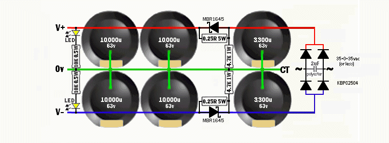
A compact crc power supply with the bypass diodes
(For one supply per channel, such as monobloc, dual mono.)

-Or-
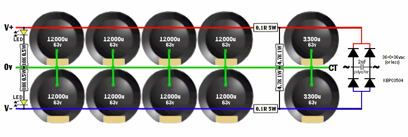
Without the bypass diodes here is an orthodox crc power supply with similar filter effectiveness

P.S.
To make it fit in the amp enclosure: Cable can be substituted for the 0.1R, such as using 2 boards (br board with first caps, then some cable, then tank/reservoir board, in which case the 0.1R-5W are not used), and that can help for easier layout but is also useful to heatsink the bridge rectifier for capacitor longevity.
Thanks Currentflow! This helps to make a more complete picture
A compact crc power supply with the bypass diodes
(For one supply per channel, such as monobloc, dual mono.)

-Or-
Without the bypass diodes here is an orthodox crc power supply with similar filter effectiveness

P.S.
To make it fit in the amp enclosure: Cable can be substituted for the 0.1R, such as using 2 boards (br board with first caps, then some cable, then tank/reservoir board, in which case the 0.1R-5W are not used), and that can help for easier layout but is also useful to heatsink the bridge rectifier for capacitor longevity.
Attachments
Okay, I did. However, that made the supply much larger. It is so different, that the application may also be different. Perhaps the larger supply suits either a stereo amp or a dual mono amp with a Much larger enclosure to fit the bulky supplies. Else not enough room to install an audio amplifier in same enclosure....But delete that spurious diode in each supply rail....
Perhaps it just shows a good reason to get a big-enough amp enclosure.
- Home
- Amplifiers
- Solid State
- diyAB Amp - The "Honey Badger"
