Why not ask Jason for a definitive answer? He doesn't bite. PM or a post in the store forum.
ok, i will tell Jason.....stand by....
Sorry for not reading nearly 1200 posts in this thread, but has anyone built a mini badger, say about 50W/8R from 35+35VDC rails? I'm looking to make a bunch of excellent quality, relatively low-power, compact amps to replace LM3886s in an active system as per this thread.
If I could get away with a single (perhaps large) output pair, that would be best for reasons of size.
If I could get away with a single (perhaps large) output pair, that would be best for reasons of size.
I would not try to reduce PS voltages that far even if in an active system. I'd go for about +/-50V and two pairs as a minimum. In my active system I'll be running HB modules from about +/-63V and three pairs of MGs.
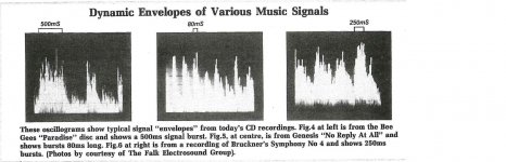
The main reason is that modern music has high signal bursts lasting even 500ms so there is no point in reducing PS voltages too much if the design allows for much higher Vs. If I do not forget I'll scan images of bursts I have in my articles and paste them here. Bob Cordell reports the same thing in his book and a few other authors do the same.
The other issue is slew rates. Actually, electronc instruments have very high slew rates. Research done by Duncan and published in Electronics World shows that a 250W amp requires at least 220V/us to reproduce such signals faithully. I'm quoting these figures from memory so it may not be exactly to the watt or Volt but roughly that's the magnitude. Stochino also noted that and designed an amp with SR over 300V/us. HB has not such high SR anyway.
cheers,
musical transients
Attachement shows music signal bursts taken from recorded CD music. These can last even hundreds of ms and their amplitude is many times higher than the average signal, especially the short bursts can have very high amplitude. Not to clip peaks with average listening level of 90-92dB at 2m distance from speakers one needs 200-600W amp into 8 ohm depending on speakers' sensitivity. Most commercial speaker systems have sensitivity about 87-88dB at 1m and usually speakers are 4 ohm to measure better as 2.83V signal is used now in such tests. In old times it was test signal for 8ohm speakers as that was equivalent of 1W delivered. So the other solution is to have high sensitivity speaker system - over 96dB at 1m.
ATJ, if you add 10ms plus peak signal detection circuit and try to listen to music from SACDs and CDs averaging 92dB at 2m you will see how often your amp is clipping short but high amplitude signals. Most people will not hear clipping of short bursts but will hear longer bursts. That is why it's practically better to have less powerful but high voltage transformers than powerful low voltage ones. With ample sized capacitors it will work well for short bursts. Important are caps on the board - these should be low ESR low ESL.
cheers,
Attachments
Last edited:
Yes it would be nice to have a TO-3 version out put stage. I have over 200 new from same run transistors. Something that used an Aluminum L bracket holding OP's to PCB and the other side of L connecting to flat side of HS, other side finned.
Correct, I do not bite
") The Honey Badger has been more a labor of love than any form of profitable exercise...
The Honey Badger has been more a labor of love than any form of profitable exercise...The latest boards, V2.4 (thank you very much OST!) have just hit the store and are available now. They will start shipping today to those who have been waiting for them to arrive and have back orders.
Further modifications to the board are welcome, but we need to sell the current batch out before doing a new one. We ordered 50 and 16 were back ordered from about the last 6 months so there's 34 remaining. That should last between 6 months and a year or so, depending on how many people get excited about building it. The best thing that could happen for the badger would be for us to produce an article or detailed sales page to promote its virtues to fresh blood - if anyone is interested in helping to make it easier to promote please let me know as we are sorely missing that part of the puzzle at the moment.
Attachement shows music signal bursts taken from recorded CD music. These can last even hundreds of ms and their amplitude is many times higher than the average signal, especially the short bursts can have very high amplitude.
Those diagrams show only the envelope and not the spectral content of the signal. I strongly suspect that the huge majority of the power spikes is in the lower frequencies so for my application (MF and HF amps for a 3-way active system), I don't think there will be any real problem with reduced rails. My LF amps are very badger-like (the Si-Chip ultra-low distortion amp) with 50V rails.
I'm being lazy here of course and I should go run an FFT over some of my favourite tracks but I haven't done that yet. So take my assumptions with a big grain of salt...
Glad to hear the v2.4 is here.
Besides having "fatter" rail traces/through plated holes , the baker clamp diode
is a good addition.
This diode should be a BAV20-21 (100nA reverse leakage). Some other diodes
are in the pA leakage range .... look for 250nA or lower as the THD suffers
otherwise.
The zener referenced cascode is default , the "R-C-Z" option pads and screenprints
are well marked and no scraping is required.
Pad masks , lead spacing , and any other slight "bugs" discussed in the build
thread are eliminated in the V2.4.
The v2.4 could not be easier to build for a class AB project. A chip amp or single
device Pass amp are the only simpler projects I can think of.
OS
Sorry for not reading nearly 1200 posts in this thread, but has anyone built a mini badger, say about 50W/8R from 35+35VDC rails? I'm looking to make a bunch of excellent quality, relatively low-power, compact amps to replace LM3886s in an active system as per this thread.
If I could get away with a single (perhaps large) output pair, that would be best for reasons of size.
Since the badger is CCS based , it will run down to 30V rails.
IPS CCS will still be 3mA , VAS CCS will still be 7-8mA.
PS - I've used a badger like IPS board to run JUST a mje15032/33 pair
as a HEADPHONE amp (20-0-20V) !
OS
Those diagrams show only the envelope and not the spectral content of the signal. I strongly suspect that the huge majority of the power spikes is in the lower frequencies so for my application (MF and HF amps for a 3-way active system), I don't think there will be any real problem with reduced rails. My LF amps are very badger-like (the Si-Chip ultra-low distortion amp) with 50V rails.
I'm being lazy here of course and I should go run an FFT over some of my favourite tracks but I haven't done that yet. So take my assumptions with a big grain of salt...
Long bursts are power hungry but short bursts may have very high amplitude and can be high frequency. I have a diode based display in my preamp. It covers 60dB range. It shows rms average and peaks 30mS plus. You'd be surprised how often peaks are well above 20dB over the average. Shorter peaks are not detected.
With +/-50V PS and 3 way active one should be pretty safe at even more than average listenning levels and such PS I suggested. HF amp can be OK with lower PS voltages if cut off frequency is a few kHz. My 3 way systems are really 3 way active plus passive between mid and HF. Sub up to 80-100Hz, Low: 80-100Hz to 650-850Hz and mid-high above so I need higher voltages on mid-high amps as well.
I have many amps including less ppowerful ones for mid and high frequencies ran from 300VA 2x30V toroids (dc is about 2x42V) and these amps can be overdriven on ocassions. Party level "noise" is not for them.
cheers,
Have the nano and pico been swapped?............. the baker clamp diode
is a good addition.
This diode should be a BAV20-21 (100nA reverse leakage). Some other diodes
are in the pA leakage range .... look for 250nA or lower as the THD suffers
otherwise...............
Low leakage is the requirement for the Baker clamp.
pico is smaller than nano.
Better yet, run a histogram on the music file. You can overlay a load line/SOA/clip across the histogram and that will show you how much margin you have, and how dynamic the music is, how likely to clip. You could even get fancy and create an SOA/thermal/clip/PSU model in simulation, run your music through that, and then do a histogram on the output to find out how how high you can push the volume before clipping.
That's much of the problem........ short bursts may have very high amplitude and can be high frequency..............You'd be surprised how often peaks are well above 20dB over the average. Shorter peaks are not detected.
..........
Many do not appreciate just how high the voltages can go in the treble frequencies.
Some Members will not accept this and repeatedly put me down for stating this treble voltage requirement.
Many are very familiar with the average power content of the various frequency bands. Some of these many misuse this average information to predict the voltage requirement of the treble only amplifier. This is wrong.
The transients are by definitions short term. Being transients that are short term demands that they are high frequency.
The treble driver should be able to reproduce sound SPL at roughly the same SPL level of the middle driver and roughly the same level as the bass driver.
It is this last statement that brings out the objectors.
I will repeat Janusz quote
how often peaks are well above 20dB over the average. Shorter peaks are not detected.
I did some actual PSD analysis on real music. Let's go argue about it over there and leave the badgers to their cull
Have the nano and pico been swapped?
Low leakage is the requirement for the Baker clamp.
pico is smaller than nano.
The reason I used nA and Picoamp was because of the simulations.
The bav20's spec states nA , it simulates as pA. That is just one model.
My reason for the 250nA recommendation - simulating my various diode
models... showed 250 was where one could just notice a degradation
at PPM level/20K. Using stock 1Nxxxx diodes is not an option , these
simulate at the uA level and cause a major THD increase.
I have not acquired any pA level diode models , but have seen various SMD
devices rated as such. The SMD's might be good to upgrade a V2.2/2.3 PCB.
My BAV20/21 are good enough for V2.4 , they just add a few PPM.
OS
What about this one: 1n3595?
I've just found it.
Spice Model:
* 1N3595
******
*SRC=1N3595;1N3595;Diodes;Rectifier;150V 0.150A 3us CS CS
.MODEL 1N3595 D (
+ IS=407.36E-12
+ N=1.7759
+ RS=.28325
+ IKF=9.7936
+ CJO=3.5499E-12
+ M=.29569
+ VJ=.3905
+ ISR=10.010E-21
+ NR=4.9950
+ BV=180.16
+ IBV=.52023
+ TT=144.27E-9)
***
cheers,
I've just found it.
Spice Model:
* 1N3595
******
*SRC=1N3595;1N3595;Diodes;Rectifier;150V 0.150A 3us CS CS
.MODEL 1N3595 D (
+ IS=407.36E-12
+ N=1.7759
+ RS=.28325
+ IKF=9.7936
+ CJO=3.5499E-12
+ M=.29569
+ VJ=.3905
+ ISR=10.010E-21
+ NR=4.9950
+ BV=180.16
+ IBV=.52023
+ TT=144.27E-9)
***
cheers,
Last edited:
Good diode !
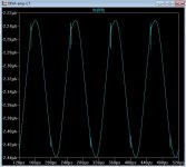
The 1n3595 shows 400pA leakage with small signal/no input and
1-2uA at full power(below) .
The BAV is much better , 30pA/500pA .... but this would do in a pinch.
THD is doubled from 15ppm to 32ppm ... but this is not a "gross"
degradation.
PS - glitches in plot is OPS X-over point feedback.
OS
The 1n3595 shows 400pA leakage with small signal/no input and
1-2uA at full power(below) .
The BAV is much better , 30pA/500pA .... but this would do in a pinch.
THD is doubled from 15ppm to 32ppm ... but this is not a "gross"
degradation.
PS - glitches in plot is OPS X-over point feedback.
OS
Attachments
Last edited:
- Home
- Amplifiers
- Solid State
- diyAB Amp - The "Honey Badger"