Toshiba output BJT's
My suggestion for the output BJT's, they are very good, tested many times.")
SC 5359 - Transistor 2SC 5359 - 2SC-Transistoren bei Reichelt Elektronik
SA 1987 - Transistor 2SA 1987,Si-P,230V,15A,180W,30MHz - 2SA-Transistoren bei Reichelt Elektronik
My suggestion for the output BJT's, they are very good, tested many times.
SC 5359 - Transistor 2SC 5359 - 2SC-Transistoren bei Reichelt Elektronik
SA 1987 - Transistor 2SA 1987,Si-P,230V,15A,180W,30MHz - 2SA-Transistoren bei Reichelt Elektronik
Attachments
Alex, could you share your PCB design? The version of post # 87...... I have rerouted somes parts from PCB, including grounding circuit , I hope now it's better ...
Thanks,
Daniel.
2STC5949/2STA2121 OP tranis
Hi ostripper,
i would like to use the earlier mentioned 2STC5949/2STA2121. Just one pair. Does this require any changes in the driver or VAS stage? Will the THD be much different?
Does anybody know about SPICE models of the 2STC5949/2STA2121?
Hey , 5'th
Holy poop!! ... those are the outputs !!!!
http://www.st.com/internet/com/TECHNICAL_RESOURCES/TECHNICAL_LITERATURE/DATASHEET/CD00171942.pdf
woweeee 4A DC soa at 60V. 7.5A /60v 100ms. Those blow the 21193/4's away but with 100+ Hfe.
you would have a growling beast of a 200/350W 8/4 R amp there. That would be conservative, even. 1 pair of these exceed 2 pair of the 5200/1943's easily.
So , a "growling beast" of an amp with (below 1) .... just "fine tuned" both the BJT and FET versions of the cascoded input stage (same" perfect circuit").
quite the FFT , almost audiophile. A slight tradeoff in PPM's for better distortion products.
Simulated with high inductance supplies / resistance to get the ripple a ripplin' , did the "worst case" scenario at 100v p-p/10k ... still nice.
OS
Hi ostripper,
i would like to use the earlier mentioned 2STC5949/2STA2121. Just one pair. Does this require any changes in the driver or VAS stage? Will the THD be much different?
Does anybody know about SPICE models of the 2STC5949/2STA2121?
jojo, you can get this NTC resistors from discarded atx psu's, the ones from an enermax 375watters or the HEC's as fine specimens....
Old CRT monitors have bigger NTCs to share!
OS, you talked about some drivers going Colpitts. About what frequency is this? I want to try modeling it in LTSpice to see if I can find a solution that will improve performance.
I like the idea of using multiple low-power fast outputs, such as the 2SC4883A. But that is just me.
I don't think ground planes are suited for the signal/feedback path; not much use here and threatens to interfere. Instead I would cut out the ground plane around the signal path and use a separate signal ground which will join the ground plane at a star point. It looks like I've missed the train though.
I like the asymmetrical rails.
Also, not to self-promote, but something like my K-multipliers would be a very effective on-board rail filtering solution.
- keantoken
Cool,
If for eg. more than 150 - 250mA would be needed which semis would You recommend to be most appropriate in Yours particularly circuit ?
If R5 & R6 will be changed for trimmers, than fine tuning of Op. Voltage would be possible and after fine adj. under working condition than can be replaced with fixed R value for each trimmer?
Cheers,
A.
Post 188 there is a zip file with BOM and everything else.Anybody know where the BOM is? I checked the whole thread, could not find.
What's the expected cost per channel, without PS?
http://www.diyaudio.com/forums/solid-state/192431-class-ab-amp-diyaudio-19.html
Regards
Simon
The K-multiplier is just like a cap multiplier; it doesn't regulate voltage, just filters it. So fine adjustment of output voltage would not mean anything.
In most cases there is little reason to not use BC550C/560C for the drivers. The output transistor should be as fast as possible, and it's Hfe high enough that at max expected current draw, the driver won't see more than 20mA. In the past I recommended 2SC5171/A1930, but these are much slower than the datasheet specifies (unless the pair Syn08 got are fakes). For currents up to 100mA I recommend the 2SC4793/A1830. For currents over that I recommend the MJE180/170. These should work for the currents you specify.
For most cases heatsinking should not be necessary.
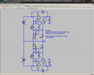
Attached is the schematic I recommend for this amp. The LED should be treated as a voltage source, and should be increased so that the ripple from the rails does not regularly clip the regulator. Two things can be changed due to the low current draw; the output transistor can be a BC550C/560C, and R2/R4 can be 10k, so a smaller filter cap can be used. R1/R3 should be through testing to determine the best value; I suggest to start with 390R.
- keantoken
In most cases there is little reason to not use BC550C/560C for the drivers. The output transistor should be as fast as possible, and it's Hfe high enough that at max expected current draw, the driver won't see more than 20mA. In the past I recommended 2SC5171/A1930, but these are much slower than the datasheet specifies (unless the pair Syn08 got are fakes). For currents up to 100mA I recommend the 2SC4793/A1830. For currents over that I recommend the MJE180/170. These should work for the currents you specify.
For most cases heatsinking should not be necessary.
Attached is the schematic I recommend for this amp. The LED should be treated as a voltage source, and should be increased so that the ripple from the rails does not regularly clip the regulator. Two things can be changed due to the low current draw; the output transistor can be a BC550C/560C, and R2/R4 can be 10k, so a smaller filter cap can be used. R1/R3 should be through testing to determine the best value; I suggest to start with 390R.
- keantoken
Attachments
- Home
- Amplifiers
- Solid State
- diyAB Amp - The "Honey Badger"