best first step is to add regulated PS for LTP and VAS 3-5V higher than power rails voltage.
Which would you rather clip , the VAS or the output stage ??
OS
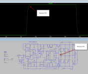
One thing I noticed when I was testing the loop gain was that even when I had 80° of phase margin I was still getting a high frequency oscillation of around 2.5Mhz in the output stage. Attached are my images of the real thing and on the simulator.
Both show the same behaviour. Try it for yourself with and without C2 and test using a high frequency pulse square wave.
As you can see there is no overshoot in the oscillation which indicates that there is still sufficient loopgain in the major loop the maintain stability.
HB 2.0 sounds awesome.
Both show the same behaviour. Try it for yourself with and without C2 and test using a high frequency pulse square wave.
As you can see there is no overshoot in the oscillation which indicates that there is still sufficient loopgain in the major loop the maintain stability.
HB 2.0 sounds awesome.
Attachments
I will "fix" Badger 1.0 first.
A lot can be learned in 9 years.")
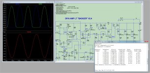
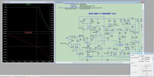
Attached is an updated Badger with 2016 Keentoken and Cordell models.
Put the KT-Cordell models.txt in the same folder as the DIYA-amp-LT.asc.
This is the 2012 original simulation of the Badger (with my changes).
I noticed with the new more accurate models that the badger was a (near)
oscillator.
From the Slewmaster and my EF3 "adventures" , I removed the driver
basestoppers (R34/35). I also reduced the VAS gain (note R22/R23) and
used a 68pF conventional miller comp.(C8 ...eliminated C7).
The results are posted below - .0029% at 20khz , and 75-80degree phase margin
at unity gain.
What is cool is that this amp is quite similar to the uPC1342 - "Badger on a chip".
My simulation seems to reflect the Sony uPC amp perfectly - the sony
rates as 800k UG/with .01%THD 20k ... Badger has more outputs , less THD.
The Sony also just uses CMC (68pF).
OS
A lot can be learned in 9 years.
Attached is an updated Badger with 2016 Keentoken and Cordell models.
Put the KT-Cordell models.txt in the same folder as the DIYA-amp-LT.asc.
This is the 2012 original simulation of the Badger (with my changes).
I noticed with the new more accurate models that the badger was a (near)
oscillator.
From the Slewmaster and my EF3 "adventures" , I removed the driver
basestoppers (R34/35). I also reduced the VAS gain (note R22/R23) and
used a 68pF conventional miller comp.(C8 ...eliminated C7).
The results are posted below - .0029% at 20khz , and 75-80degree phase margin
at unity gain.
What is cool is that this amp is quite similar to the uPC1342 - "Badger on a chip".
My simulation seems to reflect the Sony uPC amp perfectly - the sony
rates as 800k UG/with .01%THD 20k ... Badger has more outputs , less THD.
The Sony also just uses CMC (68pF).
OS
Attachments
Last edited:
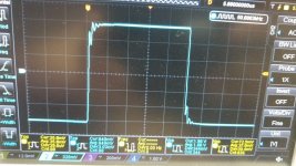
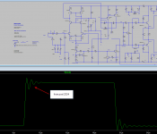
One thing I noticed when I was testing the loop gain was that even when I had 80° of phase margin I was still getting a high frequency oscillation of around 2.5Mhz in the output stage. Attached are my images of the real thing and on the simulator.
Both show the same behaviour. Try it for yourself with and without C2 and test using a high frequency pulse square wave.
As you can see there is no overshoot in the oscillation which indicates that there is still sufficient loopgain in the major loop the maintain stability.
HB 2.0 sounds awesome.
Guess what - that 2mhz + "peak" is R34/35 . I saw that on my simulation. Wow !!
Edit lowering the gain and using the 68pF CMC really eliminated it.
OS
Thanks for your input on this OS. I will definitely test this modification out and get back to everyone with some images of the square wave response and the distortion levels. Who would have thought that removing the base stoppers would have eliminated that HF oscillation. Increasing the VAS emitter resistors to increase the local feedback and made it more linear was a good thing to try as well. I'm glad that you are happy with those results.Guess what - that 2mhz + "peak" is R34/35 . I saw that on my simulation. Wow !!
Edit lowering the gain and using the 68pF CMC really eliminated it.
OS
P.s. what polk speakers do you have?
I used to have a pair of RT16's but upgraded a few years ago to RTi A5's
They do sound great with the HB. Better than my Rotel RB 1095
SON of Badger -2021 .... 9 years later
Sooooo many amps , so little time. DiYA can have this one on the house .
Just want to see happy woofers and tweeters.
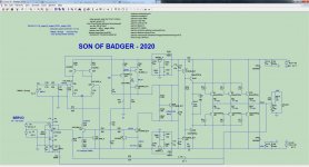
Well , here it is (below).
1. Cascoded BC560 beta enhanced VAS with matching Toshiba 5W devices.
Runs at 4ma - most likely won't need that stupid VAS heatsink.
2. "Slewmaster" EF3 - Don't need to prototype these -
many, many, slewmaster's attest to that. With 3 pair outputs ,the oversized drivers
might also need no heatsink (unless with 3 pair MT-200 sankens and
brutal 2R subwoofer duty). A small heatsink with all other uses. The slewmaster
also has a second Vbe on the drivers . The Harmon- Kardon amp that inspired
this OPS uses a small to-126 on the driver pair HS to quickly respond to
thermal changes. The original HK amp just sandwiched this second Vbe
between 2 raw drivers.
3.Same CCS's as the original badger. Classic "blameless".
4.Ah , cap multipliers. This Badger walks on water in the PSSR department.
5. Servo - Heck with offset trimmers and closely matched LTP's .
Still working on it. VERY nice to have a 16 core PC to use LT on - wow!!
(Intel Xeon V3 DDR4 system - 32Gb ram),
ALL ideas are most welcome !
OS
Sooooo many amps , so little time. DiYA can have this one on the house
.Just want to see happy woofers and tweeters.
Well , here it is (below).
1. Cascoded BC560 beta enhanced VAS with matching Toshiba 5W devices.
Runs at 4ma - most likely won't need that stupid VAS heatsink.
2. "Slewmaster" EF3 - Don't need to prototype these -
many, many, slewmaster's attest to that. With 3 pair outputs ,the oversized drivers
might also need no heatsink (unless with 3 pair MT-200 sankens and
brutal 2R subwoofer duty). A small heatsink with all other uses. The slewmaster
also has a second Vbe on the drivers . The Harmon- Kardon amp that inspired
this OPS uses a small to-126 on the driver pair HS to quickly respond to
thermal changes. The original HK amp just sandwiched this second Vbe
between 2 raw drivers.
3.Same CCS's as the original badger. Classic "blameless".
4.Ah , cap multipliers. This Badger walks on water in the PSSR department.
5. Servo - Heck with offset trimmers and closely matched LTP's .
Still working on it. VERY nice to have a 16 core PC to use LT on - wow!!
(Intel Xeon V3 DDR4 system - 32Gb ram),
ALL ideas are most welcome !
OS
Attachments
P.s. what polk speakers do you have?
I used to have a pair of RT16's but upgraded a few years ago to RTi A5's
Tsi 200's in my party room. And a modified Polk 10" sub +Thonet and Vander
bookshelves for my PC/HTPC (that 16 core beast).
Ohh , RTi A5's are Nice !!!! I've gone the small bookshelf/Sub route.
OS
The datasheet curves are identical to the Onsemi BC547 datasheet.
https://www.onsemi.com/pub/Collateral/NST65011MW6-D.PDF
https://www.onsemi.com/pub/Collateral/BC546-D.PDF
They used the curves for the BC547 but they have the Vce rating of the BC546. I suspect someone just got confused when putting the datasheet together. In any case the matching is not so good that it would be much better than picking BC546B randomly.
If you were to look into SMD monolithic matched pairs, the Nexperia PMP4201 devices might be a bit for interesting. Matched to within 2%, versus 10% for the NST65011. Similar gain and better noise figures. Though lower Vce of 45V.
https://assets.nexperia.com/documents/data-sheet/PMP4201V_G_Y.pdf
https://assets.nexperia.com/documents/data-sheet/PMP4201V_G_Y.pdf
It's not monolithic, the datasheets state the transistors are fully isolated internally. The 2mV matching is the same as the OnSemi pair and is not very impressive at all. The 2% Hfe matching could be useful, but you have to ask how does that help for the amplifier on the bench.
The noise figure specs are garbage like usual, either off the wall values or test conditions totally irrelevant to what we want to use them for.
The noise figure specs are garbage like usual, either off the wall values or test conditions totally irrelevant to what we want to use them for.
....hole openings are not just tight they are unnecessarily pinhole tight....
Carbide PCB Drill Bit - 0.5mm ID: 2118 - $1.95 : Adafruit Industries, Unique & fun DIY electronics and kits
The datasheet curves are identical to the Onsemi BC547 datasheet.
https://www.onsemi.com/pub/Collateral/NST65011MW6-D.PDF
https://www.onsemi.com/pub/Collateral/BC546-D.PDF
They used the curves for the BC547 but they have the Vce rating of the BC546. I suspect someone just got confused when putting the datasheet together. In any case the matching is not so good that it would be much better than picking BC546B randomly.
Thanks keantoken!
Unfortunately not suitable for matched pair in amplifiers...
output stage
Leach took steps so that the output stage clipped earlier than the VAS, another way perhaps is to supply the vas with higher rails than the output stage...
Which would you rather clip , the VAS or the output stage ??
OS
Leach took steps so that the output stage clipped earlier than the VAS, another way perhaps is to supply the vas with higher rails than the output stage...
You want to clip somewhere the energy won't be stored and come out later in sticking, latching or spiking. It's not always the same, even for similar looking schematics or even the same amp with different component values.
Or maybe some sticking is acceptable if it allows for better performance in reasonable listening conditions.
It all depends on what is on the bench, and the purposes you have for it...
Or maybe some sticking is acceptable if it allows for better performance in reasonable listening conditions.
It all depends on what is on the bench, and the purposes you have for it...
A lot can be learned in 9 years.
Attached is an updated Badger with 2016 Keentoken and Cordell models.
Put the KT-Cordell models.txt in the same folder as the DIYA-amp-LT.asc.
This is the 2012 original simulation of the Badger (with my changes).
I noticed with the new more accurate models that the badger was a (near)
oscillator.
From the Slewmaster and my EF3 "adventures" , I removed the driver
basestoppers (R34/35). I also reduced the VAS gain (note R22/R23) and
used a 68pF conventional miller comp.(C8 ...eliminated C7).
The results are posted below - .0029% at 20khz , and 75-80degree phase margin
at unity gain.
What is cool is that this amp is quite similar to the uPC1342 - "Badger on a chip".
My simulation seems to reflect the Sony uPC amp perfectly - the sony
rates as 800k UG/with .01%THD 20k ... Badger has more outputs , less THD.
The Sony also just uses CMC (68pF).
OS
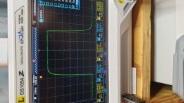
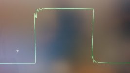
Hi OS, Thank you for sharing that circuit in post 2224. I tested the circuit that you attached with a 100Khz pulse and removing C2 and I still see the same behavior.
In fact it appears to be worse that what I was seeing in the simulation that I was running on the original schematic. What are your thoughts OS?
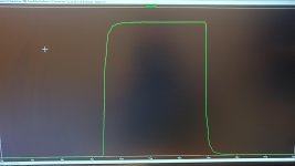
When I remove the Output stage completely and connect the NFB to the drivers the output is perfect.
Attachments
Last edited:
From memory I believe that one output pair is fine. Its once you start to parallel them that the oscillation startsBypassing R23 helps.
- Home
- Amplifiers
- Solid State
- diyAB Amp - The "Honey Badger"