
Hello Everyone,
I'm just starting this project, but firstly I simulate it. I have question about current source on the IPS. Could you explain why current on R14 is 3.75 mA? Is there any forum/video which explain in detail honey badger amplifier?
Thank you
Jérôme
There is a video series started on the design of this amp. SW Audio - YouTube It started out good but has evolved into a LTSpice tutorial. Hopefully it moves on from there.
It started out good but has evolved into a LTSpice tutorial.
Its far from a ltspice tutorial
Oscillation
I build a pair of HB amp.
The supply is + / - 60V and the clipping occurs at 36,2 V Eff on 8,25 Ohms that is 158 W.
One works fine and I have no problem with. The second one which is an exact copy made simultaneously encounters small issue.
1- At first power on, everything seems correct, voltage across 10 Ohms resistors and so on. When adjusting idle current with R 30, measuring across TP1 and TP2, you can adjust at 18 mV and then the level jump to 100 / 200 mV. Impossible to adjust the desired value.
This was without anything at input and output.
With an 8 Ohms Load at the output terminal you can adjust easily at 22 mV which represents 50 mA by power transistor, the idle current I want to use.
With 50 mA, no crossover distorsion and the THD is reasonably low. I measure 0,015 % THD at 1 KHz and 40 W... and it sounds fine... So I am happy !
2- On the second unit, when power output increases, an oscillation appears in the upper part of the signal. The oscillation arrives when you reach 90 W and stays until max power and clipping = 158 W.
So, I try different things and finally increase the value of C 18 by paralleling a 10 pF capacitor and then the oscillation only occurs around 130 W.
Bandwith doesn't seem to be modify.
But the oscillation remains just before clipping.
Any idea about such issue ?
Nice amp.
Advantages -
- less VAS current , far less load on VAS. could be run w/ no VAS heatsink.
Output load has no effect on VAS / w EF3. THD is less than w/EF2.
Disadvantages - needs slightly more rail V (3 Vbe drops - EF3) ... more
complicated.
In light of this , and using standard OEM speakers ..... The Badger/
wolverine differences would be hard to discern. I offered the Wolverine
as just another option for a input stage/VAS to compare to the
current feedback offerings.
Badger = textbook / better than OEM , easy + well documented.
10ppm vs. 5ppm would be nearly inaudible.
PS - I use the different/better ? CCS + the same BAVxx clamp diode
(on the wolverine) ,
this would amount to only an academic improvement. Only a
totally different topology would amount to any change in "character" ?
Hi ostripper, janusz,
When I simulate HB-LT_jpv24volv1.asc from post #1254. The sim appears to work fine with THD really low.
I wanted to adjust the bias; disconnecting and shorting the input to ground and disconnection the output (which I believe is correct), after adjusting R7, I adjusted R30 and for some reason get around 7 Amps across the Emitter resistors no matter how much I vary R30, so no chance of getting 100mA!
Taking into consideration it took a great deal of hunting to find all the model.txt files, there may be errors there but all I did was copy paste.
You'll probably tell me to stick with the basin Honey badger but I wanted to compare the differences between the two first with the sim. The standard HB sim works fine!
I'm probably making an amateur mistake!
Any ideas ? (6 years later
") )
)
Last edited:
Oscillation
Hi everybody
Maybe Mr. Ostripper have time to takea look.
I continue on the problematic channel and discover different things.
To be completely honest, I got a problem with this channel since the beginning due to a mistake. My eyes are quite poor and I use magnifying glass to check and insert componaents.
On this channel even with magnifying glass, I insert a MJE 15033 for Q 14 in place of a MJE 15032.
When powering on, the 10 Ohms security resistors go to smoke !
Thank you for this precaution Mr. Ostripper.
I was of course disappointed, but I dismantle the amp and re-check all components. I saw my mistake and, after verifying one pair of power transistors which were good, I replace immediately Q9, Q10, Q11, Q12, Q13, Q14 & Q15. And also C9 because it is a 22 µF with 35V isolation. After controlling a lot of resistors, I finally power on the unit.
No problem, 0,160 V on the 10 Ohms security resistors and no voltage across TP1 and TP2.
I adjust R17 Offset on output, then R7 for LTP current and finally the idle current with R 30.
Curiously, it was not possible to adjust the current correctly. When you reach 18 mv between TP1 and TP2, then voltage drop to 150 / 200 mv. So I readjust r 30 to stay around 15 mv.
Security resistors have been removed an fuses inserted.
I then connect à 8,25 Ohms / 200W on output and a generator at input.
In this condition, I mean with a load, the idle current can be adjusted as you wish. Good point… but maybe not so good because the idle current is not stable and the reaction is quite confusing. If you apply + 1 dB at input then you obtain 158 W output. If you switch input to ground the current between TP1 and TP2 decrease slowly and finally drop to 10 mV. After a while it finally stabilizes around the correct value of 30 mV.
When you switch on the amp with no input signal the idle current is too high. At power on the voltage across TP1/TP2 reach 120 to 150 mV before decreasing to 20 mV and then arrives at 30 mV.
I check the other channel which responds properly. When you stop signal current goes down immediately and at power on the current reach rapidly the correct value without “hesitation”.
Oscillation.
On this channel oscillation occurs.
Oscillation with power but not only.
If you take a careful look at the oscilloscope you find a small oscillation around the zero crossing of the signal at certain frequencies and power.
At very low power : nothing. Around 10 to 20 W output oscillation appears and stay until reaching more than 100W. Then disappears. And the oscillation only occurs between 500 Hz and 3 KHz.
There is surely something wrong somewhere due to my “original” mistake but I don’t know where to look.
I am not sure that the input stage has suffered.
My problem today is in relation with idle current and zero crossing. All that things are in relationship with the power transistors. I only check a pair of output transistors.
I have maybe to replace “all” the output transistors !
Idea and suggestion are welcome.
Sorry to be so long
Best regards
Attachments
Hi ostripper, janusz,
When I simulate HB-LT_jpv24volv1.asc from post #1254. The sim appears to work fine with THD really low.
I wanted to adjust the bias; disconnecting and shorting the input to ground and disconnection the output (which I believe is correct), after adjusting R7, I adjusted R30 and for some reason get around 7 Amps across the Emitter resistors no matter how much I vary R30, so no chance of getting 100mA!
Taking into consideration it took a great deal of hunting to find all the model.txt files, there may be errors there but all I did was copy paste.
You'll probably tell me to stick with the basin Honey badger but I wanted to compare the differences between the two first with the sim. The standard HB sim works fine!
I'm probably making an amateur mistake!
Any ideas ? (6 years later
Funny, I started from scratch and it's all working now. Maybe I corrupted something whilst adding the directives to the sheet! Now I can compare the differences. All that remains apart from committing to build is tidy up all the duplicate models in my files.
Cheers.
I build a pair of HB amp.
The supply is + / - 60V and the clipping occurs at 36,2 V Eff on 8,25 Ohms that is 158 W.
One works fine and I have no problem with. The second one which is an exact copy made simultaneously encounters small issue.
1- At first power on, everything seems correct, voltage across 10 Ohms resistors and so on. When adjusting idle current with R 30, measuring across TP1 and TP2, you can adjust at 18 mV and then the level jump to 100 / 200 mV. Impossible to adjust the desired value.
This was without anything at input and output.
Any idea about such issue ?
Nice amp.
I had same experience with DIY Naim amplifier. It is found out that the negative feedback circuit open.
Honey Badger Trouble Shooting.
Hi folks I have read the complete thread here at DYI, a ton of experience and information. Very thankful for all your experience. I have built a few amps in my time, however I am no way any shape an expert at electronics, its a great hobby for me.
I am having issues with the Build I have the new boards 2.4 from the Dyi store bought all the parts from Mouser or DigiKey. I have double check triple checked the placement of the parts, but to no avail I have something messed up and I cant figure what it is.
When I power it up with a bulb tester, the bulb does not glow, the two leds light up. And my voltage on the 10 ohm instead of fuses goes up past 1 volt quickly, the Tp1 and Tp2 millivolts low to zero or negative.
DC offset reading from the Speaker output to ground voltage goes up as I increase the voltage from the variac, and the bulb will light as I increase the variac, but goes out as the caps charge and no adjustment will change it. When and I can start to smell a burning so I turned it off quickly.
I used all the parts from the BOM listed on the Dyi audio store site. The BOM is confusing due to the age of it in relation to the newest Sch dated 12/22/2016, some of the resistors are different there.
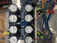
PSU is Dyi Audio board 3 with Antek 10445 dual transformer, NTE35 amp rectifiers Dual, All caps are from DigiKey 80v 10,000uf. The PSU checks out fine with the rails being 63v 0v -63v.
I must have a transistor installed incorrect, I have check all these and double check the components. I built both boards at the same time installing the components per location on each board after verifying the part. Both boards do the same thing. The leads me to believe I must have the same misplacement but I can't seam to find it no mater how many times I check it. I did have to use MPSA18 instead of SS-9014 I saw some folks with issues there.
Any suggestions on where and what to look at would be greatly appreciated.
Hi folks I have read the complete thread here at DYI, a ton of experience and information. Very thankful for all your experience. I have built a few amps in my time, however I am no way any shape an expert at electronics, its a great hobby for me.
I am having issues with the Build I have the new boards 2.4 from the Dyi store bought all the parts from Mouser or DigiKey. I have double check triple checked the placement of the parts, but to no avail I have something messed up and I cant figure what it is.
When I power it up with a bulb tester, the bulb does not glow, the two leds light up. And my voltage on the 10 ohm instead of fuses goes up past 1 volt quickly, the Tp1 and Tp2 millivolts low to zero or negative.
DC offset reading from the Speaker output to ground voltage goes up as I increase the voltage from the variac, and the bulb will light as I increase the variac, but goes out as the caps charge and no adjustment will change it. When and I can start to smell a burning so I turned it off quickly.
I used all the parts from the BOM listed on the Dyi audio store site. The BOM is confusing due to the age of it in relation to the newest Sch dated 12/22/2016, some of the resistors are different there.
PSU is Dyi Audio board 3 with Antek 10445 dual transformer, NTE35 amp rectifiers Dual, All caps are from DigiKey 80v 10,000uf. The PSU checks out fine with the rails being 63v 0v -63v.
I must have a transistor installed incorrect, I have check all these and double check the components. I built both boards at the same time installing the components per location on each board after verifying the part. Both boards do the same thing. The leads me to believe I must have the same misplacement but I can't seam to find it no mater how many times I check it. I did have to use MPSA18 instead of SS-9014 I saw some folks with issues there.
Any suggestions on where and what to look at would be greatly appreciated.
Attachments
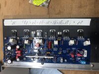
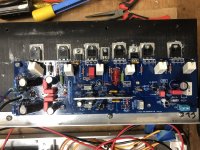
I notice the aluminum plate heatsink is quite a bit wider than recommended. Not an issue, but I do know the legs of the transistors and the passive components close by have very little clearance even with the thin aluminum plate. Double check nothing is shorting against the plate.
What I meant is the thickness of the plate is quite a bit thicker. I think the OP used a .040 to .060 inch thickness, yours looks to be about 1/8 or thicker. 1/8 would be .125 inch.
I used 3mm or 0.12" on my 5ch. that's no problem. I did have to check the clerance tho.
Misterwinefine:
And i belive the problem is with Q9. check Q3-6 and Q9-10. Make sure it is right transistors at the right place. And check if they are all okei.
Last edited:
- Home
- Amplifiers
- Solid State
- diyAB Amp - The "Honey Badger"