one reason is if you got fakes...
i have lots of cases repairing Sansui G-series amps wherein the output trannies fried and the drivers still live,
only the associated resistors got burned out, some resistors did not even show signs of burning, they were flameproof...
These MGs come from element14 directly from the UK so it's very unlikely that they are fakes. Drivers come from Mouser and were made in Malaysia.
Well, burned output transistors and drivers surviving is usually connected with ouput being shortened. I don't think it happened to me. No resistors were burned except these parallel to fuses.
cheers,
Janusz, I am following this all with keen interest, like you I am trying to learn why this may have happened...
Your reasoning is clear to me thus if the outputs were shorted the insulators must have failed, no?
I have done this kind of thing myself but by using an electrically conductive heat paste. Maybe in your case the bolts or the mica conducted???
Your reasoning is clear to me thus if the outputs were shorted the insulators must have failed, no?
I have done this kind of thing myself but by using an electrically conductive heat paste. Maybe in your case the bolts or the mica conducted???
bending the loop wire
The loop is the problem.
The Flow Route through the resistor body should be close coupled to the Return route via that exposed wire.
Fold the Return wire close to the body of the resistor. That small loop area makes it less inductive and less of a transmitter.
Unfortunatly it is impossible .... At the time I did not use common copper wire ...I did want something stiff and I used some copper plated steel, very difficult to bend ... they keep resistors standing vertical and on opposite side I use them to connect protection circuit wire.
I see now that you already checked the micas...I'm just trying to think outloud about what should be fine but isn't. I keep finding a false assumption at the heart of my unexplained issues with electronics

This was the first module I built and for two weeks it was often switched on with globe in series of course and everything was fine. If it tended to oscillate globe would show it. The worst thing is not knowing why it happened.
cheers,
My guess is something either shorted or over heated. Every amp I have built, showed higher bias, once the light bulb was removed from the circuit. Maybe it just took that extra amperage to reveal it. Once you get the parts replaced, fire it up on the light bulb to make sure there are no big problems and then remove the light before you try raising the bias and watch very, very closely as you raise it. I would monitor both rails as I did. Make sure you have a good tight, flat contact with each device. OS can tell you if the amp is prone to oscillation but mine never acted up in that way. Good luck.
Blessings, Terry
Blessings, Terry
LED polarity check
somebody help?
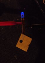
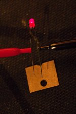
I was installing a red and blue LED on the HoneyBadger board being very careful of polarity as the guide rightfully suggests and it put me in a quandary…
Web guides say the long leg of the LED is Positive, smaller interior section (electrode) of LED is positive and the schematic marking for positive is the broad perpendicular side of the triangle (opposite the flat perpendicular "bar") is positive. Cool. Except my two LEDs would beg to differ.
Using the diode setting on my DMM almost none of the above is consistently true IF a lighted LED is the best indication of which end is positive and which is negative. (YES I have checked the markings on my DMM and even measured a battery to make sure things are correct with the DMM")
SO, go with the lighted LED as best indicator, yes?
May I assume too the LEDs are not uniform in their construction cuz I'm going to be crazy if I don't get this all to make sense.
note: in each picture the left lead (red) has the larger electrode
somebody help?
I was installing a red and blue LED on the HoneyBadger board being very careful of polarity as the guide rightfully suggests and it put me in a quandary…
Web guides say the long leg of the LED is Positive, smaller interior section (electrode) of LED is positive and the schematic marking for positive is the broad perpendicular side of the triangle (opposite the flat perpendicular "bar") is positive. Cool. Except my two LEDs would beg to differ.
Using the diode setting on my DMM almost none of the above is consistently true IF a lighted LED is the best indication of which end is positive and which is negative. (YES I have checked the markings on my DMM and even measured a battery to make sure things are correct with the DMM
SO, go with the lighted LED as best indicator, yes?
May I assume too the LEDs are not uniform in their construction cuz I'm going to be crazy if I don't get this all to make sense.
note: in each picture the left lead (red) has the larger electrode
Attachments
5mm LEDs have a flat on the flange.
That flat indicates -ve.
My 3mm and smd leds do not have a flat.
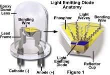
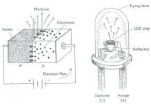
The -ve lead connects to the big "bowl" inside the LED. A clear LED, even red coloured LEDs, allows you to see the bowl. The +ve connects to a very fine wire that leads into the middle of the bowl.
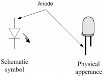
The schematic diagram shows a bar on the end of the diode arrow.
All these -ve indicators are consistent.
Big Bowl, flat on flange, black bar on arrow, they are all -ve.
BTW, your blue LED pic shows the "bowl" connected to the red croc clip. This confirms that the "conventional current is flowing from black croc clip to red croc clip.
Can you see the "bowl" in your red LED?
Can you see a "flat" on any of your LEDs?
That flat indicates -ve.
My 3mm and smd leds do not have a flat.
The -ve lead connects to the big "bowl" inside the LED. A clear LED, even red coloured LEDs, allows you to see the bowl. The +ve connects to a very fine wire that leads into the middle of the bowl.
The schematic diagram shows a bar on the end of the diode arrow.
All these -ve indicators are consistent.
Big Bowl, flat on flange, black bar on arrow, they are all -ve.
BTW, your blue LED pic shows the "bowl" connected to the red croc clip. This confirms that the "conventional current is flowing from black croc clip to red croc clip.
Can you see the "bowl" in your red LED?
Can you see a "flat" on any of your LEDs?
Last edited:
I understand the flat...
Hey Andrew,
I understand the flat mark as an indicator (ve-) in this case they are 3mm LEDs and have none. The plastic bubble around the electrodes is colored but I can see the structure inside (see: pic). In both cases the "bowl" is the positive electrode (ve+). You can see the markings under the blue one; I have kept the LEDs in the same orientation all through all my photos to be sure I am seeing what I am seeing. The ve+ is on the left as is the large "bowl". They light up this way; it must be "correct" even though it goes against convention.
You can see the legs length as polarity determination is not holding true in the earlier photos too.
I guess all I need to have confirmed is that there is not truly consistent standard for LEDs so one must apply power in both polarities/directions to be sure.
If testing for polarity is what was said most commonly on the web I'd take it for truth but what I find most directions match what you have said Andrew (with the addition of the leg length thing)...yet my experience does not jibe.
Arrrgh.
Anybody else out there have contradictory experience like mine? As a new guy (this is my second amp build) I have a tendency to doubt myself keenly. Yet my evidence is pretty clear...to me. How about you?
For the record I am a pretty long way off from applying power to my HB boards but I have reviewed the tracings to make sure of the polarity - the board is correct. The part numbers for these two leds: blue is c4smk-bjs-cq0t0352 (mouser) red: 160-1035-ND (digikey).
It took me a long time to learn that To-92 packages are inconsistent for CBE; I'm trying to save time with LEDs
Attachments
The large "bowl" on the left of your LEDs is connected to the more negative voltage to allow current to flow.
A diode that is BLOCKING current flow takes the -ve lead to the more positive voltage.
An LED passes current to light up. It needs the -ve lead to be more negative to allow that current to pass.
A diode that is BLOCKING current flow takes the -ve lead to the more positive voltage.
An LED passes current to light up. It needs the -ve lead to be more negative to allow that current to pass.
Last edited:
To92 package is just the package. There are dozens of stanrds for that package size. You need to correctly identify the manufacturer of each device and use that manufacturer's datasheet to determine the leadouts..................It took me a long time to learn that To-92 packages are inconsistent for CBE; I'm trying to save time with LEDs
However, some BJTs are instantly identifiable.
BC are cbe. Except when they have an L suffix.
2sa & 2sc are ecb, as are those BCxxxL from above. As far as I know there are no exceptions.
2n and Eline are different.
Test your LED with a 9V pp9 and a ~2k2 resistor. It will flow ~3mA and do no harm. Once you have convinced yourself, go back to your multi-meter and determine which lead is +ve and which is -ve.
It might change between resistance and diode functions.
flow, no flow
Bless you Andrew for your patience. I am an artist by disposition and a teacher by trade so I have a weird mix of logic and not. I TRY to imagine electrons racing around a schematic but I'm a long way from being able to predict where they actually go. You post helps. Thank you.
Thus what I am trying to do here is build something then without a complete understanding of how it works. "Just enough information to be dangerous" don't you know... And if I thought I was alone in this universe of dim understanding I'd shut up and not ask silly questions.
Nor am I surprised that info posted on the net is contradictory What I am hoping for is a way not to screw up building this thing I don't fully understand: the Honey Badger and all future things I might want to attempt. I want to follow directions!
So, to assist all those out there who are like me, trying to learn by remote how to do something useful I am trying to get to the bottom of a perplexing thing (for me) a lack of consistency in how a gizmo is connected to its PCB: a simple LED.
It seems to this novice that the cathode of an LED must be connected to the NEG or ground for an LED to work, right? I should put the cathode into the PCB at the "bar" end of the symbol...
Yet the cathode (the bowl or larger electrode in my red and in my blue LEDs) is connected to the positive lead on my DMM and the LED lights up. This would indicate to me to install that larger electrode, that cathode (cathodes seem to be consistently marked (-) right?) into the board where I have, at the base of the triangle of the LED symbol (this is the anode side of the symbol!)
Am I just NOT understanding how my DMM works?
I have included some of the inconsistent images I have found of LED construction/designations; I have not found the LED symbol itself to be inconsistently labeled for cathode and anode so I trust that.
I'd like to just insert the longer lead into the anode end of the symbol but no can do: my two LEDs do not match for how they light up, one lit with the long lead to red (ve+) of my DMM and the other lit with short lead to (ve+).
I'd like to look into the construction of an LED and know which electrode to put into the "bar" end (cathode end) of the symbol. If the larger electrode is the cathode (-) then I could put that end into the PCB at the "bar" end (cathode end) but... then why do my LEDs light up when that larger electrode (cathode?) is connected to the red (ve+) end of my DMM? (Obviously I cannot use the short leg theory and in this case there is no flat to indicate cathode).
Forgive the iteration, I'm just looking for a rule. If the dern thing lights up, insert the lead that was on the red clip of the DMM into the anode side of the PCB symbol right? And forget about construction, lead length etc
Bless you Andrew for your patience. I am an artist by disposition and a teacher by trade so I have a weird mix of logic and not. I TRY to imagine electrons racing around a schematic but I'm a long way from being able to predict where they actually go. You post helps. Thank you.
Thus what I am trying to do here is build something then without a complete understanding of how it works. "Just enough information to be dangerous" don't you know... And if I thought I was alone in this universe of dim understanding I'd shut up and not ask silly questions.
Nor am I surprised that info posted on the net is contradictory
What I am hoping for is a way not to screw up building this thing I don't fully understand: the Honey Badger and all future things I might want to attempt. I want to follow directions!So, to assist all those out there who are like me, trying to learn by remote how to do something useful I am trying to get to the bottom of a perplexing thing (for me) a lack of consistency in how a gizmo is connected to its PCB: a simple LED.
It seems to this novice that the cathode of an LED must be connected to the NEG or ground for an LED to work, right?
I should put the cathode into the PCB at the "bar" end of the symbol... Yet the cathode (the bowl or larger electrode in my red and in my blue LEDs) is connected to the positive lead on my DMM and the LED lights up. This would indicate to me to install that larger electrode, that cathode (cathodes seem to be consistently marked (-) right?) into the board where I have, at the base of the triangle of the LED symbol (this is the anode side of the symbol!)
Am I just NOT understanding how my DMM works?
I have included some of the inconsistent images I have found of LED construction/designations; I have not found the LED symbol itself to be inconsistently labeled for cathode and anode so I trust that.
I'd like to just insert the longer lead into the anode end of the symbol but no can do: my two LEDs do not match for how they light up, one lit with the long lead to red (ve+) of my DMM and the other lit with short lead to (ve+).
I'd like to look into the construction of an LED and know which electrode to put into the "bar" end (cathode end) of the symbol. If the larger electrode is the cathode (-) then I could put that end into the PCB at the "bar" end (cathode end) but... then why do my LEDs light up when that larger electrode (cathode?) is connected to the red (ve+) end of my DMM? (Obviously I cannot use the short leg theory and in this case there is no flat to indicate cathode).
Forgive the iteration, I'm just looking for a rule. If the dern thing lights up, insert the lead that was on the red clip of the DMM into the anode side of the PCB symbol right? And forget about construction, lead length etc
Attachments
There is another very simple method if you haven't yet populated your board and have PS operational. Just solder light diode resistors (R51 and R53) and R32-33. In the next step solder in fuse holders, populate with fuses and solder V+ and V- terminals and the ground terminal. Place your PS in series with a globe, connect your PS to the board (+, - and ground). Touch board diode pads with tested diode pins. If it glows that is the way it should be soldered in, if it does not just reverse pins and it will glow.
You can do the same test with a battery and R51,53,32 and 33 temporarily shortened. For the red diode connect batery + with V+ terminal and batery - to the ground. Touch pins of red diode with its soldering pads to getr the glow. To test the blue diode, connect batery - with V- and connect battery + with the ground. Find the correct polarity. The latter test can be safely done if your boards are populated.
cheers,
we're all right, some LEDs ARE reversed
OK guys, I am convinced I am not crazy nor are any of you who thought I was…
I tested a few other types of LEDs I had on hand that I never used because I found "better" (brighter). They are 751-1139-ND (digikey number) , VAOL-5GDE4 (mouser) and 593-VAOL-5LDE2 (mouser) and a fourth type I got in bulk from a friend. All of the above tested as you would expect and is most commonly posted with the larger electrode functioning as cathode.
I went over this three times this morning checking both with a battery plus resistor as Andrew suggested and with my DMM. The two I originally posted are the odd ducks and work in reverse!
Dang! How did I get so lucky :-( to pull out a pair like that?
So, I'd hope no one else gets ahold of odd ducks. blue is c4smk-bjs-cq0t0352 (mouser) red: 160-1035-ND (digikey) Of course, there may be more
Bob Ellis had it right, short and sweet: if it lights up you're not crazy!
PS. I'll ship these crazy makers to anyone who needs them, otherwise I'm trowing them away!
Explosive outputs:
The other honey badger thread documented an outbreak of this, and one or more changes prevented the problem. It was either the "luxeman way" without the zener and/or it was disabling the TMC that prevented the outputs from blowing. I don't remember which. Check for yourself somewhere in this thread: http://www.diyaudio.com/forums/solid-state/192431-diyab-amp-honey-badger.html
Guesswork:
I also made some notes in that thread about some onsemi devices that don't match by half (especially the drivers), and you might want to check that out. Just because a top name brand distributor has authentic parts doesn't mean the bulk order was filled from the same fab plant, and that is how *some* authentic parts can perform as bad or worse than fakes.
Wild guess: Maybe a combination of off spec transistors causes the TMC to glitch.
Backwards LED's:
As for LED's, routinely, some LED's are internally backwards. Except, usually, the clear body Red, Orange, Yellow are not backwards. However, it is highly likely for anything else to be backwards, especially phosphate coated lighting grade LED's--Those are always backwards from classic red/orange. And all of the markings, yes, also backwards. I just checked one of my lighting boards, which have 2 cool white, 1 warm white, 1 orange to simulate normal (and 3+3+3+2v=11v=minimum waste on a 12v supply), and anyway, the internals of the orange are visibly opposite orientation, because the rest are backwards. They're supposed to be.
Thanks daniel, would you remember roughly where in this thread? - as it has over 120 pages.
Maybe I'll as in that thread.
I use Semelab MGs from element14 UK. Both N and P channels were matched very closely at 10mA. I have never heard about MG fakes but that does not mean that fakes are not made and sold.
cheers,
Maybe I'll as in that thread.
I use Semelab MGs from element14 UK. Both N and P channels were matched very closely at 10mA. I have never heard about MG fakes but that does not mean that fakes are not made and sold.
cheers,
Last edited:
- Home
- Amplifiers
- Solid State
- diyAB Amp The "Honey Badger" build thread