I would suggest that you try it. I haven't had any electronic training but I do have a multimeter. I just hooked up one side of the secondary of a 44-0-44vac transformer to a bridge rectifier. With 44vac going into the bridge I get 39Vdc output. With caps attached I see 62Vdc.
a Transformer feeding just the bridge rectifier outputs a rectified sinewave.
The voltmeter reads the average voltage of that rectified sinewave. This is a bit less than the rms voltage of the sinewave.
If smoothing capacitors are fed from the rectifier, the voltage available from the transformer tries to charge the capacitor to the peak voltage on the sinewave less the Vdrop of the rectifier. The capacitor/s can't discharge back through the (perfect) rectifier.
If there is no output current the voltmeter reads the average of the capacitor charge voltage, which within a couple of cycles of the mains, will be equal to sqrt(2) times the sinewave - 2*Vf
Vf at very low current is likely to be less than 500mVdc.
2 times Vf is thus likely to be less than 1Vdc.
Redjr, With most DMMs the DC voltage without filter caps will appear to be roughly the same as the RMS AC voltage. What the smoothing caps do is hold the average value closer to peak, which is where the 1.41 comes from.
EDIT: Sorry for piling on. AndrewT said it better than me, as usual.
EDIT: Sorry for piling on. AndrewT said it better than me, as usual.
NP. I stand corrected. I guess there are more rusty memory cells lying on the floor of my brain than I thought. I knew they were accumulating, just not this rapidly.Redjr, With most DMMs the DC voltage without filter caps will appear to be roughly the same as the RMS AC voltage. What the smoothing caps do is hold the average value closer to peak, which is where the 1.41 comes from.
EDIT: Sorry for piling on. AndrewT said it better than me, as usual.
") I guess I have always measured the voltage after the caps too, so shouldn't have mis-spoke. My bad.
I guess I have always measured the voltage after the caps too, so shouldn't have mis-spoke. My bad.
Last edited:
I'll ask a friend of mine to take a look at it during the weekend but I do not think there is any wiring error as it worked without any problems and nothing has really changed since then. The only difference is that soft start switch is now hard wired, while before it was connected to a switch, which might have created this problem but I have no idea what happened.
Theoretically, there may be a problem with my soft start unit but I checked all its components. With caps centre rails connected to the ground it does not switch on. I have such soft start unit working perfectly well switchin on two 300VA toroids. Toroid in this PS is 500VA.
l
cheers,
i think that you have several issues at the same time, so try to solve each one separately, one by one...
with your lamp tester, you can solve the psu problem first, (disconnect the soft start board in the meantime)...
once you have this sorted out, then you can fix the soft start circuit...
Thanks for ideas.
First I'll measure voltage drop between these two capacitor banks. I may try to swap AC connections to one of the bridges but if colour markings on the secondaries are correct then current wiring is correct and this PS worked fine for say close to 10 minutes. Then I switched it off and switched on again and it still worked then if I remember correctly. It was the third time when it stopped workig possibly because I changed wiring on the switch (disconnected illumination connection). Then it failed.
Having checked everything again I'll disconnect the soft start.
Writing this I've just realised one thing. It's likely that the problem is with the soft start as the kit most likely came with parts and diagram for 120V and I forgot to change one resistor and one cap values to make it operational with our 240V, which can be anything between 225V and over 255V. That's why coil burned in the first one. The other soft start unit works partially. I put it together a few months ago. I suspect the resistor has the correct value for 250V but probably I forgot to change the cap value from 330nF to 1.2uF. When I get back home I'll check.
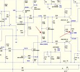
Circuit is attached with my markings. It also shows a ground connection but there is no ground pin on its board and its bridge is referenced to neutral so I do not think it has to be grounded. The one working for a couple of years in another amp has correct part values for 240V mains as then I remembered that some part values had to be changed.
cheers,
First I'll measure voltage drop between these two capacitor banks. I may try to swap AC connections to one of the bridges but if colour markings on the secondaries are correct then current wiring is correct and this PS worked fine for say close to 10 minutes. Then I switched it off and switched on again and it still worked then if I remember correctly. It was the third time when it stopped workig possibly because I changed wiring on the switch (disconnected illumination connection). Then it failed.
Having checked everything again I'll disconnect the soft start.
Writing this I've just realised one thing. It's likely that the problem is with the soft start as the kit most likely came with parts and diagram for 120V and I forgot to change one resistor and one cap values to make it operational with our 240V, which can be anything between 225V and over 255V. That's why coil burned in the first one. The other soft start unit works partially. I put it together a few months ago. I suspect the resistor has the correct value for 250V but probably I forgot to change the cap value from 330nF to 1.2uF. When I get back home I'll check.
Circuit is attached with my markings. It also shows a ground connection but there is no ground pin on its board and its bridge is referenced to neutral so I do not think it has to be grounded. The one working for a couple of years in another amp has correct part values for 240V mains as then I remembered that some part values had to be changed.
cheers,
Attachments
the soft start ckt, puts a series resistor with you traffo primary for a few seconds to minimize turn on surge current....
a 24 volt zener to clamp the dc voltage is a better tweak than the 470ohm resistor change,
the 68R resistor can be a 20 watter for long term reliability....
a 24 volt zener to clamp the dc voltage is a better tweak than the 470ohm resistor change,
the 68R resistor can be a 20 watter for long term reliability....
Puzzle solved, at least this one. It is this soft start unit, which creates all these problems. I have no idea what is going on in it. Actually these two units i tried with this PS are junk. But the old soft start unit works.
Anyway, without any of these two soft start units this PS seems to work well, positive and negative voltages were both 66.1V with the centre (+ and - of both capacitor banks connected) grounded.
So now I'm without a soft start. I have to ask Stanton what are the right values of components for 240V. On the other hand I do not know if it's worth using a soft start with 500VA toroid. Maybe plugging NTC in live wiring between the mains and the toroid? Does it make sense? I never used NTCs but I have some sg333s in my box. So far I've been using these to connect amp's ground with the mains ground.
cheers,
Can't tell from your photos which exact soft-start you're using, but here's one from a reputable source that may work better.Puzzle solved, at least this one. It is this soft start unit, which creates all these problems. I have no idea what is going on in it. Actually these two units i tried with this PS are junk. But the old soft start unit works.
Anyway, without any of these two soft start units this PS seems to work well, positive and negative voltages were both 66.1V with the centre (+ and - of both capacitor banks connected) grounded.
So now I'm without a soft start. I have to ask Stanton what are the right values of components for 240V. On the other hand I do not know if it's worth using a soft start with 500VA toroid. Maybe plugging NTC in live wiring between the mains and the toroid? Does it make sense? I never used NTCs but I have some sg333s in my box. So far I've been using these to connect amp's ground with the mains ground.
cheers,
Soft-start
No, I've never seen this one but without seeing a circuit diagram and hearing opinions of those who use it it might be another cat in a sack. The one I was using is very simple (diagram attached in one of my posts above) and the first one I built over two years ago is still working well.
cheers,
cheers,
One problem solved but another appeared. As PS is OK I have connected the first amp module without power transistors. Instead of R36 and C20 there are two 68 resistors from emitters of Q14 and Q15 to the output line. PS connection is done through two 12 ohm resistors.
PS voltages on the amp's rails are +/-64.37V (difference between - and + below 10mV). Voltage drop on R14 is 7.5V and I set offset to 0.7mV. Then I started to adjust bias as ostripper recommended to get about 550mV drop on R34 and R35 which gives about 25mA to bases of Q14 and Q15.
And here I get a problem. Reducing resistance of R30 does not do almost anything. On R34/35 I got a drop of 1.2mV at one point and then it stayed at this level until the end = ZERO on R30 (shorted).
VAS transistors on aluminum plate get pretty warm, Q13, 14 and 15 get warm but not very, Q7-8 get warmer than Q13-15. No change in other voltages. Globe is not emitting any light.
Changes I made are in VAS transistors and resistors as recommended by os: R12=6.8k and R13=7.5k, while C5=110uF. I do not have 2sc3503 so Q13 is ksc2690y, Q14 and 15 are Toshibas 2sa1930/c5171 with 30pF micas. VAS transistors are: Q9=2sa970bl and Q10-12 are 2sa1209s/c3211s.
VAS is warmer as it gets more current in that configuration but why bias setup circuit does not work?
cheers,
PS all transistors are from Mouser or directly from Fairchild.
PS 2 in that soft start circuit 470 ohm/1.2uF are for 110V; for 240V these should be 220 ohm and 560mF and these were the values I used. Sorry for my wrong description of the unit.
Last edited:
Looked at your problem.
The combo of those drivers + the increased VAS I , brought you
beyond the range of the Vbe. That's all.
Look below - I have your sa1930/sc5171 models.
Much higher gain with these drivers .... in fact , so much gain/Ft - 120-150hfe
(triple the MJE's) !
You could run your VAS at 4-5ma as your driver/OP setup has
almost EF3 type current gain.
lower R29 and/or R36 (68-100R) as shown.
PS - you might need to go R29 (470R) to get to the middle of "Vbias" (250R) with those
drivers.
OS
(below).
Attachments
Last edited:
Thanks ostripper,
My 2sa/sc drivers have Hfe about 150 at Ic=2.5mA.
OK, I'll solder another resistor to the other side of the pcb to get about 470 ohm on R29 and reduce R36 to about 100 ohm but at the moment R36 and C20 are not in.
Once that is done what voltage drop should I set across R34 (and R35) without power transistors in to safely power the amp when my output MGs are in???
Thank you,
cheers,
PS my mje15xxxx also seem to have higher gain than typical. As far I remember I measured about 70-80 and about 120-140 so the minimum Hfe discrepancy I could get between N and P was about 50%. In the end I opted for 2sa1930/c5171.
for as long as your output offset voltage is no more than +-100mV
and that you are able to set bias, then you are good to go...
as i said, i just preset the pots to what Ostripper recomended,
the offset pot to mid span, and off i went....
this amp will work the first time.....
assuming no wiring mistakes....
and that you are able to set bias, then you are good to go...
as i said, i just preset the pots to what Ostripper recomended,
the offset pot to mid span, and off i went....
this amp will work the first time.....
assuming no wiring mistakes....
Thanks ostripper,
My 2sa/sc drivers have Hfe about 150 at Ic=2.5mA.
OK, I'll solder another resistor to the other side of the pcb to get about 470 ohm on R29 and reduce R36 to about 100 ohm but at the moment R36 and C20 are not in.
Once that is done what voltage drop should I set across R34 (and R35) without power transistors in to safely power the amp when my output MGs are in???
Thank you,
cheers,
PS my mje15xxxx also seem to have higher gain than typical. As far I remember I measured about 70-80 and about 120-140 so the minimum Hfe discrepancy I could get between N and P was about 50%. In the end I opted for 2sa1930/c5171.
R34/35 are the basestoppers for the drivers ?? No voltage drop.
R36 can be a good test point use 2 33-47R temporarily soldered to the
pads .... derive NFB from in between those 2 resistors.
Adjust the bias to get .5 -.6V from NFB to the emitters of the drivers.
(1.0 -1.1 V across driver emitters total)
At this point , a pair of OP's connected will be unbiased (not conduct).
trim the bias ... ON's start conducting at about .6+ V
PS - if you mean the voltage between E-C of the Vbe ... it should be 2-2.2V ,
properly biased OP's - about 2.4V. This is dependent on driver/OP type.
OS
- Home
- Amplifiers
- Solid State
- diyAB Amp The "Honey Badger" build thread