For some time now i have been considering my options on how to construct a volume control. Im not talking about a simple pot or even motorized. Im thinking something in this direction:
Basically the nearest match to my project is the VC-03.
I have been considering different options, such as building this from scrap or using a audio processor on the market, with I2S bus interface. It raises one essential question, should one stick to the simple audio processor or build the unit from scrap?
I have many years of experience with embedded programming and decent electronics skills, both practical and theoretical. Unfortunately i'm not super sharp at developing PCB's and simulating.
Basically my objective with this thread is to see if it has any interest, and if thats the case start up a open-source project.
LINKS
vicol audio
Hifiduino
AmpDuino
Reload this Page My Preamp Project: Arduino, I2C, relay selector+attenuator, tube stage
SUGGESTIONS
LCD
Microcontroller (wo/screen)
Microcontroller (w/ screen)
Volume control
Audio selector
N/A yet.
(*) First choice
SYSTEM DESIGN:
The design i had in mind is attached in a self-explaining picture, please comment on this.

- Volume control (w/ mute)
- Switcher board
- LCD screen
- IR receiver
- Microcontroller with input from smooth encoder
Basically the nearest match to my project is the VC-03.
I have been considering different options, such as building this from scrap or using a audio processor on the market, with I2S bus interface. It raises one essential question, should one stick to the simple audio processor or build the unit from scrap?
I have many years of experience with embedded programming and decent electronics skills, both practical and theoretical. Unfortunately i'm not super sharp at developing PCB's and simulating.
Basically my objective with this thread is to see if it has any interest, and if thats the case start up a open-source project.
LINKS
vicol audio
Hifiduino
AmpDuino
Reload this Page My Preamp Project: Arduino, I2C, relay selector+attenuator, tube stage
SUGGESTIONS
LCD
- Standard 16x2/20x4 1602 HD44780 (Aliexpress etc.) ~3-8$
Microcontroller (wo/screen)
- TI MSP-EXP430F5529LP 12.99$
Microcontroller (w/ screen)
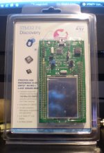
- STM32F429 Discovery ~23$
Volume control
Audio selector
N/A yet.
(*) First choice
SYSTEM DESIGN:
The design i had in mind is attached in a self-explaining picture, please comment on this.
Last edited:
Check out the PGA2311 or the LM11972.
The PGA2311 has a wider range.
Audio - Volume Control - PGA2311 - TI.com
Audio - Volume Control - LM1972 - TI.com
For switch's and multiplexers there are lots of great ones to chose from LT, TI and AD.
I just discovered AD's AD75019 16 X 16 crosspoint switch with 256 individually controlled switches.
This device could handle the inputs and outputs of 8 stereo device connected in any possible way of combinations.
AD75019 datasheet and product info | The AD75019 Contains 256 Analog Switches in a 16 x 16 Array | Analog Crosspoint Switches | Analog Devices
I am starting to embark on such a project myself for a patch bridge for my Multitrack recording system.
As a control you may want to look at that has everything you may need is ST's STM32F429IDiscovery board as they are only about 33$.
32F429IDISCOVERY Discovery kit for STM32 F429/439 lines - with STM32F429ZI MCU - STMicroelectronics
Once I start too learn how to use this thing it is going to open up a whole knew world for me as I haven't done any programming since the 8-Bit days of Basic.
It is an incredible little board and has a 800 X 600 color TFT touch screen as well.
It is a cool little board for what it is.
I liked it so much I got two more of them!!!
After doing a webinar about them on EE Times,
You can find the archives here,
(you have too scroll all of the way to the bottom of the page)
http://www.eetimes.com/lecture-calendar.asp?cid=eetimes_website_lecturelist
My main goals is to build my own digital recorder for just recording with little to no editing required.
All that is needed is to mimic the function of the recorder and at no lees that 24bit 192Khz.
Analog tape is great but getting parts for my aging deck has its days numbered as it now needs $200+ worth in just two rubber wheels!!
If I can find them !!!!!
Not to mention the cost of each reel of tape.
FWIW
jer
Attachments

Last edited:
Check out the PGA2311 or the LM11972.
The PGA2311 has a wider range.
Audio - Volume Control - PGA2311 - TI.com
Audio - Volume Control - LM1972 - TI.com
For switch's and multiplexers there are lots of great ones to chose from LT, TI and AD.
I just discovered AD's AD75019 16 X 16 crosspoint switch with 256 individually controlled switches.
This device could handle the inputs and outputs of 8 stereo device connected in any possible way of combinations.
AD75019 datasheet and product info | The AD75019 Contains 256 Analog Switches in a 16 x 16 Array | Analog Crosspoint Switches | Analog Devices
I am starting to embark on such a project myself for a patch bridge for my Multitrack recording system.
As a control you may want to look at that has everything you may need is ST's STM32F429IDiscovery board as they are only about 33$.
32F429IDISCOVERY Discovery kit for STM32 F429/439 lines - with STM32F429ZI MCU - STMicroelectronics
Once I start too learn how to use this thing it is going to open up a whole knew world for me as I haven't done any programming since the 8-Bit days of Basic.
It is an incredible little board and has a 800 X 600 color TFT touch screen as well.
It is a cool little board for what it is.
I liked it so much I got two more of them!!!
After doing a webinar about them on EE Times,
You can find the archives here,
EE Times University
My main goals is to build my own digital recorder for just recording with little to no editing required.
All that is needed is to mimic the function of the recorder and at no lees that 24bit 192Khz.
Analog tape is great but getting parts for my aging deck has its days numbered as it now needs $200+ worth in just two rubber wheels!!
Not to mention the cost of each reel of tape.
FWIW
jer
Lovely and rich comment you came with. We have those Discovery units at our campus, but i have not tested them yet. But for 23$ with a onboard QVGA screen and Cortex-M4 its pretty reasonable. Only thing that can worry me is the screen quality, GUI designer and the complexity of getting the screen up running, but i assume you can come with a input on that. One thing is for sure, the price is extremely low for that much hardware, cant even complain!
I will click through the switchers and volume control, looks pretty interesting!
I designed a USB mixer that used digital pots.
IT was 6 channels.
It also had digital bass and treble controls.
Worked very well, eventually lol
The first pcb was poorly laid out in regards to the power supply and I got loads of hum.
On the second pcb I starred the audio and power supply grounds and then it was fine.
IT was 6 channels.
It also had digital bass and treble controls.
Worked very well, eventually lol
The first pcb was poorly laid out in regards to the power supply and I got loads of hum.
On the second pcb I starred the audio and power supply grounds and then it was fine.
I designed a USB mixer that used digital pots.
IT was 6 channels.
It also had digital bass and treble controls.
Worked very well, eventually lol
The first pcb was poorly laid out in regards to the power supply and I got loads of hum.
On the second pcb I starred the audio and power supply grounds and then it was fine.
Could you toss a link on the pots? Thanks
It is all new to me but going through the small course they touched on all of that and they did some demos of how to change things such as backgrounds and Icons and stuff with pictures of your choice.
The screen quality is much much better than what I could get my camera to produce a picture of (sorry about that)!!
They said it will play a movie from off of a USB card but haven't even started using it yet.
IARsystems only has a 30day trial license for there full version, and you need the full version in order to work with the demo software.
IAR sent me an Email asking me if I needed an extension but I haven't followed up on that yet, as it will be a while before I will be able to get my head wrapped around it.
But I am on a mission!!!
I did find an Open Sourced IDE platform called Code::Blocks that supports the board as well as possibly "CooCox".
But I don't know enough about this stuff yet as I am just now cutting my teeth on PIC's and MPLABx.
The only thing about the screen is that it is small at 2.5" but maybe a bigger one can be easily interfaced but it is sharp and bright for as far as I can tell.
That multiplexer is about $30 to $35 in singles but is really is cost effective for what it can do by the time you add up board space and chip count using other devices, unless you are just looking to hooking up a few components.
I have other numbers for those as well such as the DG408/9's and others in the DG4xx and DG2xx Family of switches.
I have been looking at various digital pots until I found out that they only can be used with a 0-5V or a +2.5/-2.5V signal range (Hmmmm.....).
I have thought about using some Multiplying DAC's as well for volume controls but this can become costly, I think the TI chips will suit this quite nicely.
I just got some LM1972's and I had forgot about the PGA2311's so I will try to get some of those next.
Anyhow all of the source code to the demo on the STM32F429IDiscovery is available free on ST's website and what was used in the EE Times Presentation with IARsysems IDE, all in C.
jer
Could you toss a link on the pots? Thanks
I used MCP4231.
It is a dual digital pot.
It is controlled by a serial bus.
I made a mistake on my first design in that I didn't ensure input of the pot was always biased to 2v5 and got clicks when I turned the pot on and off.
Bear in mind these pots work between 0v and 5v so they have to be biased to 2v5 with a pair of resistors on the input if AC coupled.
Other than that they were easy to use. I used a PIC18F4550 with USB bus to control the pots. The volume control and tone control were on the pc screen as sliders.
I have been looking at various digital pots until I found out that they only can be used with a 0-5V or a +2.5/-2.5V signal range (Hmmmm.....).
jer
This isn't a problem as most inputs are less than or equal to line level which is 1VRMS
If you need more gain just add an op-amp after the digital pots.
That worked well in my USB mixer.
Here are some links to digital pots,
MicroChip,
Digital Potentiometers Products - Microchip Technology Inc
AD's digital pots,
Digital Potentiometers | D/A Converters | Analog Devices
Intersil,
Digital Potentiometers | DCPs
I have one that has 6 pots on it and is only about $2 to $3 for it at cost, much cheaper than mechanical ones will cost.
You can get them as SPI or Up/Down control as the interface, Volatile an Non Volatile and from 64 tap 1024 taps.
Just the one thing that bugs me is the 0V to 5V range.
This is okay for the -10db home equipment stuff, But not my +4db mixer as it can do a full 12v/-12v swing if not more right at clipping.
jer
Yes, I have been thinking about that Nigel.
Normally my signals are only about 4Vp-p (at 0db) but what happens to the noise floor if I have to amplify it to get the voltage levels that match my systems peak levels.
I guess I will find out more when I finally get one made.
jer
Normally my signals are only about 4Vp-p (at 0db) but what happens to the noise floor if I have to amplify it to get the voltage levels that match my systems peak levels.
I guess I will find out more when I finally get one made.
jer
Yes, I have been thinking about that Nigel.
Normally my signals are only about 4Vp-p (at 0db) but what happens to the noise floor if I have to amplify it to get the voltage levels that match my systems peak levels.
I guess I will find out more when I finally get one made.
jer
I didn't attenuate any inputs. The mixer allowed a range of inputs from two microphones/guitars and 4 line level. After the digital pots was a mixer stage that also had a gain of about 4.
This worked well.
It as all a matter of proper gain structure basically.
I was just looking for a way to replace the faders for automation and this won't work on my mixer as it is.
But if a system is designed around the requirement of no more the 5Vp-p then it will work good where the devices are used, then this will work very good I think.
jer
I was just looking for a way to replace the faders for automation and this won't work on my mixer as it is.
But if a system is designed around the requirement of no more the 5Vp-p then it will work good where the devices are used, then this will work very good I think.
jer
I put the digital pots right on the inputs so it didn't clip the signal.
For gain control or?
if you want, you can grab my code for the pga chip.
search on 'amb delta 1' or 'lcduino'.
the code is primarily for a relay r2r atten but I have selection code in there for the pga, as well. I used to toy around with the pga.
these days, I won't bother anymore with that. I love the cs3318. I suggest you go with that chip instead. WAY better in so many ways.
Okay, I just measured that when my mixer has a signal on a channel that is at 0db this signal is at 4.04Vp-p.
When the signal is at -10db (as is most stereo equipment is rated for at Odb) the voltage is now 1.28Vp-p.
When I increase the voltage to a level of +10db it is now at 12.64Vp-p.
Now my mixer has a bit more headroom of above this level, clipping at 18.4Vp-p!
I rarely ever go that high with it but I commonly to as high as +10db as my absolute limit with it and that is over twice what the parts are rated for.
Therefore with common home equipment rating (-10db for 0db) it is acceptable and allows for +10db over this level.
But for Pro rated equipment you will have to attenuate the signal before you get to the variable gain block or digital pots, and then, amplify it by the same factor after the gain block in order to stay within the voltage ratings of the devices.
This was as measured on my mixer and the values are as close to approximate that I could get them by using the Cursor reading on my scope and the initial 0db reading of the meters on my mixer.
I had just went through the mixer and had determined that all of the gains and channel meters are still within spec and the attenuation settings on my signal generator are in 10db steps and I have not known for them to be to far off (if ever at all) as well.
So this was a good experiment and is some thing to keep in mind when you start to work with the mentioned devices.
Cheers !!
jer
Nice, Thanks for the tip Linuxworks!!!
Here is the data sheet to the CS3318,
http://www.cirrus.com/en/pubs/proDatasheet/CS3318_F1.pdf
jer
Here is the data sheet to the CS3318,
http://www.cirrus.com/en/pubs/proDatasheet/CS3318_F1.pdf
jer
- Status
- This old topic is closed. If you want to reopen this topic, contact a moderator using the "Report Post" button.
- Home
- Source & Line
- Digital Line Level
- DIY volume control open-source project