Re: Components......
Konnichiwa,
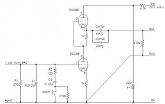
Unlikely. As shown the whole PSU filtering will give << 0.1uV RMS PSU noise and in essence 1/2 that on the output of the SRPP. Compared to a 2V RMS output for digital full scale you then have theoretically -146db for PSU line noise, the Valves themselves will produce a lot more noise, solid state power supply regulators usually produce a lot more noise than valves, so better stick to simple & predictable passive filtering.
Which "special" resistors.
The pinout needs to be accounted for etc, you may wish to adjust the cathode resistors in the SRPP Stage.
At any decently sorted component supplier.
Sayonara
Konnichiwa,
jazzpeter65 said:1. Would a regulated solid state PSU give a better signal-to-noise ratio?
Unlikely. As shown the whole PSU filtering will give << 0.1uV RMS PSU noise and in essence 1/2 that on the output of the SRPP. Compared to a 2V RMS output for digital full scale you then have theoretically -146db for PSU line noise, the Valves themselves will produce a lot more noise, solid state power supply regulators usually produce a lot more noise than valves, so better stick to simple & predictable passive filtering.
jazzpeter65 said:2. PSU: Can I substitute the special resistors for normal ones?
Which "special" resistors.
jazzpeter65 said:3. What do I have to change to use E80CC or 12Bb4H?
The pinout needs to be accounted for etc, you may wish to adjust the cathode resistors in the SRPP Stage.
jazzpeter65 said:BTW: Where can I get the following?
22uF/250v
220uF/450v
47uF/250v
At any decently sorted component supplier.
Sayonara
Hello Thorsten,
I have a question about the PSU for your tube output stage: the 210V at its output is supposedly taken with the load of 2 tubes, right?
I am a total newbie, what's the idle current of these stages (so I can calculate the PS component values with PSU designer?
Can be the 22uF capacitor connected to the pin 1 if ECC88 be electrolytic (maybe bypassed with a MKP) ?
Thank you
Andrea
I am going to try this one on my Brute force headphone amp,and even on the DAC tube stage if it works out right,I am going to build 2 of them one for each chanel as the cost is not so high,will there be any difference compared to one in chanel separation.
I am not so good at counting the values of components,Instead I build and try and ask people here who knows,but I´m learning.
I am going to use different zeners for a lower output voltage
I am not so good at counting the values of components,Instead I build and try and ask people here who knows,but I´m learning.
I am going to use different zeners for a lower output voltage
Attachments
help on some of the components for the DAC outputstage..
Sayonara,
From what I can read in your latest answer there is no nedd for a regulated PSU - I'll just stick with the one you have designed.
Before start building the DAC outputstage I need your help on some of the components:
1. By "special" resistors I mean Holco, carbon composite non-inductive resistors etc. Can I use standard resistors instead and what sonic differens will it make?
2. What are the names of the "drop-in" equivalent tubes that can substitute ECC88? Some Russian tubes maybe?
3. Like Andrea in this thread, I've found that the 22uF/400V Ansar supersound metalised polypropylen you mention is hard to get. Where can I get it? And isnt 22uf an extreamly high (non-standard) value for a propylen cap? Is there a substitute for it? (Farnell or RS number)
4. I'm wondering about the two polystyren caps: 0,012uF and 0,12uF. Must be 12nF and 120nF, right? These values are not standard. Do you have Farnell or RS numbers on them?
Best,
Peter
Re: help on some of the components for the DAC outputstage..
Konnichiwa,
First, carbon composite and Holco ARE "standard" resistors. Secondly, especially in the Powersupply the use of non-inductive resistors is fairly important.
With the SRPP as shown you merely need one switch to adjust the heater connections and you can use any of the following Valves and their equivalents (use TDSL at duncanamps.com for full equivalent listings):
12AT7, 12AU7, 12AV7, 12AX7, 12AY7, 6DJ8, 6922, 6CG7 and any of their direct and near equivalents.
I find them supremely easy to get:
www.cricklewoodelectronics.com
Well, I know off hand of at least five or six locally (UK) available Manufatcurers who have Polypropylene capacitors in such values readiluy and fairly inexpensively (compared to premium grade "audiophile" electrolytic capacitors), Ansar (UK), ICW (UK), SCR/Solen (FR), Arcotronics (IT), Ducati (IT). All these companies make polypropylene capacitors up to around 50..60uF.
Sure, plenty. Just look it up.
Yes, 0.12uF = 120nF. ANd sorry, but these Values ARE standard or can be made up from standard values by paralleling.
Please look them up yourself, you must appreciate that I have not got the time to go through catalogues for you.
Sayonara
Konnichiwa,
jazzpeter65 said:1. By "special" resistors I mean Holco, carbon composite non-inductive resistors etc. Can I use standard resistors instead and what sonic differens will it make?
First, carbon composite and Holco ARE "standard" resistors. Secondly, especially in the Powersupply the use of non-inductive resistors is fairly important.
jazzpeter65 said:2. What are the names of the "drop-in" equivalent tubes that can substitute ECC88? Some Russian tubes maybe?
With the SRPP as shown you merely need one switch to adjust the heater connections and you can use any of the following Valves and their equivalents (use TDSL at duncanamps.com for full equivalent listings):
12AT7, 12AU7, 12AV7, 12AX7, 12AY7, 6DJ8, 6922, 6CG7 and any of their direct and near equivalents.
jazzpeter65 said:3. Like Andrea in this thread, I've found that the 22uF/400V Ansar supersound metalised polypropylen you mention is hard to get.
I find them supremely easy to get:
www.cricklewoodelectronics.com
jazzpeter65 said:And isnt 22uf an extreamly high (non-standard) value for a propylen cap?
Well, I know off hand of at least five or six locally (UK) available Manufatcurers who have Polypropylene capacitors in such values readiluy and fairly inexpensively (compared to premium grade "audiophile" electrolytic capacitors), Ansar (UK), ICW (UK), SCR/Solen (FR), Arcotronics (IT), Ducati (IT). All these companies make polypropylene capacitors up to around 50..60uF.
jazzpeter65 said:Is there a substitute for it? (Farnell or RS number)
Sure, plenty. Just look it up.
jazzpeter65 said:4. I'm wondering about the two polystyren caps: 0,012uF and 0,12uF. Must be 12nF and 120nF, right?
Yes, 0.12uF = 120nF. ANd sorry, but these Values ARE standard or can be made up from standard values by paralleling.
jazzpeter65 said:Do you have Farnell or RS numbers on them?
Please look them up yourself, you must appreciate that I have not got the time to go through catalogues for you.
Sayonara
Ahem....
Hi,
May I hope you're not going to make them believe they can just pop those in?
12xx7 most adhere to the Jedec 9A standard.
6DJ8 and equivalents adhere to Jedec 9AJ which is a totally different pinout.
To be pin to pin compatible is one thing, to work is another and to work optimally is yet another story still.
As for equivalents of the ECC88/6DJ8, yes the listing at Duncan amps gives you a fair idea.
USRR nearest equivalent of the E88CC/6922 is the Sovtek branded 6922 or 6H23-P-EB.
Although marketed by Svetlana as such, the 6N1P is NOT equivalent to the ECC88.
Ideally an SRPP stage works best with a pre-known load and a stiff as a brick PS.
If not you'll notice the soundstage becoming a foggy blur.
Cheers,")
Hi,
With the SRPP as shown you merely need one switch to adjust the heater connections and you can use any of the following Valves and their equivalents (use TDSL at duncanamps.com for full equivalent listings):
12AT7, 12AU7, 12AV7, 12AX7, 12AY7, 6DJ8, 6922, 6CG7 and any of their direct and near equivalents.
May I hope you're not going to make them believe they can just pop those in?
12xx7 most adhere to the Jedec 9A standard.
6DJ8 and equivalents adhere to Jedec 9AJ which is a totally different pinout.
To be pin to pin compatible is one thing, to work is another and to work optimally is yet another story still.
As for equivalents of the ECC88/6DJ8, yes the listing at Duncan amps gives you a fair idea.
USRR nearest equivalent of the E88CC/6922 is the Sovtek branded 6922 or 6H23-P-EB.
Although marketed by Svetlana as such, the 6N1P is NOT equivalent to the ECC88.
Ideally an SRPP stage works best with a pre-known load and a stiff as a brick PS.
If not you'll notice the soundstage becoming a foggy blur.
Cheers,
Re: Ahem....
Konnichiwa,
Asolutely, if you use the circuit discussed and observe the following note in my original post:
"you merely need one switch to adjust the heater connections"
Actually, in all relevant areas the pinout is identical. You need to connect pin9 (heater centertap on 9A and shield on 9AJ) to the negative heater voltage and pin 4 to the positive heatervoltage. For 9A pinout pin 5 is switched to the positive heater voltage, for 9AJ to negative heater voltage. Works absolutely great.
The SRPP is a fairly special case and as shown a wide range of Valves can be used, if neccesary with a slight adjustment of the cathode resistors. I originally designed this stage to abel to work with a wide range of Valves on purpose, hence the Biasing is not the absolutely ideal case for 6DJ8/6922.
No, it is actually workable in most ECC88 circuits though and usually more linear.
That is the orthodox view.
I found that theroeticaly "ideal" and "good sound" do not always go hand in hand. I appreciate the work of Mr. Broskie, but I do not make the mistake to take his proof of ideal harmonic cancellation into a given fixed load asproof of "good sound".
I have failed to notice that, sorry. It actually sounds more likely that something, somewhere was slewing, given your description.
Sayonara
Konnichiwa,
fdegrove said:May I hope you're not going to make them believe they can just pop those in?
Asolutely, if you use the circuit discussed and observe the following note in my original post:
"you merely need one switch to adjust the heater connections"
fdegrove said:12xx7 most adhere to the Jedec 9A standard.
6DJ8 and equivalents adhere to Jedec 9AJ which is a totally different pinout.
Actually, in all relevant areas the pinout is identical. You need to connect pin9 (heater centertap on 9A and shield on 9AJ) to the negative heater voltage and pin 4 to the positive heatervoltage. For 9A pinout pin 5 is switched to the positive heater voltage, for 9AJ to negative heater voltage. Works absolutely great.
fdegrove said:To be pin to pin compatible is one thing, to work is another and to work optimally is yet another story still.
The SRPP is a fairly special case and as shown a wide range of Valves can be used, if neccesary with a slight adjustment of the cathode resistors. I originally designed this stage to abel to work with a wide range of Valves on purpose, hence the Biasing is not the absolutely ideal case for 6DJ8/6922.
fdegrove said:Although marketed by Svetlana as such, the 6N1P is NOT equivalent to the ECC88.
No, it is actually workable in most ECC88 circuits though and usually more linear.
fdegrove said:Ideally an SRPP stage works best with a pre-known load and a stiff as a brick PS.
That is the orthodox view.
I found that theroeticaly "ideal" and "good sound" do not always go hand in hand. I appreciate the work of Mr. Broskie, but I do not make the mistake to take his proof of ideal harmonic cancellation into a given fixed load asproof of "good sound".
fdegrove said:If not you'll notice the soundstage becoming a foggy blur.
I have failed to notice that, sorry. It actually sounds more likely that something, somewhere was slewing, given your description.
Sayonara
Hi,
So do I but that theory is still correct and is extremely logical in its approach.
If you care to cross check, Jean Hiraga and our Japanese friends who original brought the circuit back to our attention showed exactly the same.
Looking at Hiragas' SRPP phono stage you can't possibly miss the gigantic PS.
Add to that the fact that almost all SRPP circuits ideally require separate envelopes for the triodes allowing each to have its heater biased up to cathode potential and you'll see why I'm not all that convinced by this drop in a tube and forget about it thing.
Unless you want to drive them all bananas, that is...
Take it as you like but I've dabbled with SRPPs of all kinds over the passed twenty years and with all kinds of tubes and whatever the theory of operation, facts are still facts and SRPP circuits certainly are no exception to the rules.
Other than that they certainly can sound fine.
I wouldn't have bothered with them for so many years if they didn't, or would I?
Cheers,
I appreciate the work of Mr. Broskie, but I do not make the mistake to take his proof of ideal harmonic cancellation into a given fixed load asproof of "good sound".
So do I but that theory is still correct and is extremely logical in its approach.
If you care to cross check, Jean Hiraga and our Japanese friends who original brought the circuit back to our attention showed exactly the same.
Looking at Hiragas' SRPP phono stage you can't possibly miss the gigantic PS.
Add to that the fact that almost all SRPP circuits ideally require separate envelopes for the triodes allowing each to have its heater biased up to cathode potential and you'll see why I'm not all that convinced by this drop in a tube and forget about it thing.
Unless you want to drive them all bananas, that is...
Take it as you like but I've dabbled with SRPPs of all kinds over the passed twenty years and with all kinds of tubes and whatever the theory of operation, facts are still facts and SRPP circuits certainly are no exception to the rules.
Other than that they certainly can sound fine.
I wouldn't have bothered with them for so many years if they didn't, or would I?
Cheers,
Konnichiwa,
Absolutely, but it has any relevance to sonics only if the lowest THD (meaning the lowest amount of 2nd harmonics for the SRPP) equates to the best sound, which it demonstrably does not.
Actually, non of them insisted on a specifixed load and no other.
Looking at any other Hiraga Circuit you fnd the same extremely overbuild powersupplies, using unfortunatly very poor auality capacitors, hence the needs for such excess.
As long as you keep the Supply voltage low(ish) you can actually use one envelope. It is only once you seriously turn up the HT (as found in many circuits inlcuding Hiraga) that you get the usual problems normally claimed to relate to the SRPP, but in reality relating to inappropriate use of the SRPP .
Try it for a change, +B in the 200 region, heaters biased to 70V (as shown), pin 4 to positive heater voltage, pin 5 switchable +/- and pin 9 to negative Heater supply.
Completely agreed. And the SRPP shown, when equipped with the Valves suggested and realised as suggested will work well within the rules, simply because it accounts for them sufficiently. Will it be the last word in performance - no. But for that you will need to carfully tune parts and circuit to specific DAC used, nothing "universal" will ever reach that.
Sayonara
fdegrove said:So do I but that theory is still correct and is extremely logical in its approach.
Absolutely, but it has any relevance to sonics only if the lowest THD (meaning the lowest amount of 2nd harmonics for the SRPP) equates to the best sound, which it demonstrably does not.
fdegrove said:If you care to cross check, Jean Hiraga and our Japanese friends who original brought the circuit back to our attention showed exactly the same.
Actually, non of them insisted on a specifixed load and no other.
fdegrove said:Looking at Hiragas' SRPP phono stage you can't possibly miss the gigantic PS.
Looking at any other Hiraga Circuit you fnd the same extremely overbuild powersupplies, using unfortunatly very poor auality capacitors, hence the needs for such excess.
fdegrove said:Add to that the fact that almost all SRPP circuits ideally require separate envelopes for the triodes allowing each to have its heater biased up to cathode potential
As long as you keep the Supply voltage low(ish) you can actually use one envelope. It is only once you seriously turn up the HT (as found in many circuits inlcuding Hiraga) that you get the usual problems normally claimed to relate to the SRPP, but in reality relating to inappropriate use of the SRPP .
fdegrove said:and you'll see why I'm not all that convinced by this drop in a tube and forget about it thing.
Try it for a change, +B in the 200 region, heaters biased to 70V (as shown), pin 4 to positive heater voltage, pin 5 switchable +/- and pin 9 to negative Heater supply.
fdegrove said:Take it as you like but I've dabbled with SRPPs of all kinds over the passed twenty years and with all kinds of tubes and whatever the theory of operation, facts are still facts and SRPP circuits certainly are no exception to the rules.
Completely agreed. And the SRPP shown, when equipped with the Valves suggested and realised as suggested will work well within the rules, simply because it accounts for them sufficiently. Will it be the last word in performance - no. But for that you will need to carfully tune parts and circuit to specific DAC used, nothing "universal" will ever reach that.
Sayonara
Re: 12BH7 drop-in...
Konnichiwa,
If you plug the 12BH7 in as is, it will bias at around 4.5 - 5mA/100V and work just fine. But you get less gain than with a ECC88, (the stage gain is around Mu/2) so you need to change the I/V resistor to get enough output or accept that you have less output than normal.
Sayonara
Konnichiwa,
jazzpeter65 said:
Since I know that you have designed several circuits with the 12BH7A I would like to ask you what the values of the original DAC outputstage would be if I used 12BH7A instead of ECC88?
Anode voltage is 210 volts.
If you plug the 12BH7 in as is, it will bias at around 4.5 - 5mA/100V and work just fine. But you get less gain than with a ECC88, (the stage gain is around Mu/2) so you need to change the I/V resistor to get enough output or accept that you have less output than normal.
Sayonara
1. How much can I lower the V/I resistor? I assume that the Iout of PCM1704 exspect to see a minumum load?
2. What is the gain factor in db with ECC88?
3. I have two nice Siemens NOS E80CC that I would like to try also. Their mu is about 27 as opossed to ECC88 with a mu of 33.
Any need fro adjusting the cathode resistors using E80CC in the SRPP Stage?
- Peter
2. What is the gain factor in db with ECC88?
3. I have two nice Siemens NOS E80CC that I would like to try also. Their mu is about 27 as opossed to ECC88 with a mu of 33.
Any need fro adjusting the cathode resistors using E80CC in the SRPP Stage?
- Peter
1. How much can I lower the V/I resistor? I assume that the Iout of PCM1704 exspect to see a minumum load?
I have read somewhere It sometimes sound better with the right (Different value on the resistor)would it be possible to use variable resistor to find the right value?
That´s what I´m wondering 2.
Konnichiwa,
If you lower the I/V conversion resistor you will find that the output becomes lower. Thus you need more gain, implying a 12AT7 or 12AX7 in the SRPP. Hence you need to make the resistor large enough in value to get enough output while remaining below the"critical" value (critical is sually for BB DAC's a value leading to more than 0.5V peak on the DAC's output).
Not neccesarily, but yes, it is usually used that way.
The gain factor in db is 2 * LOG(Gain) where gain is a dimensionless number. The gain of a SRPP as shown is always Mu/2 as long as the load is neglible (eg 100k or 50k).
So for the ECC88 with a Mu of 33 the gain is 20 * LOG(33/2) = 24db.
Non I can see. You can experiement a little with the cathode resistor values, but it should work fine as long as you make sure the Heater Pin's are connected correctly.
Sayonara
jazzpeter65 said:1. How much can I lower the V/I resistor?
If you lower the I/V conversion resistor you will find that the output becomes lower. Thus you need more gain, implying a 12AT7 or 12AX7 in the SRPP. Hence you need to make the resistor large enough in value to get enough output while remaining below the"critical" value (critical is sually for BB DAC's a value leading to more than 0.5V peak on the DAC's output).
jazzpeter65 said:I assume that the Iout of PCM1704 exspect to see a minumum load?
Not neccesarily, but yes, it is usually used that way.
jazzpeter65 said:2. What is the gain factor in db with ECC88?
The gain factor in db is 2 * LOG(Gain) where gain is a dimensionless number. The gain of a SRPP as shown is always Mu/2 as long as the load is neglible (eg 100k or 50k).
So for the ECC88 with a Mu of 33 the gain is 20 * LOG(33/2) = 24db.
jazzpeter65 said:3. I have two nice Siemens NOS E80CC that I would like to try also. Their mu is about 27 as opossed to ECC88 with a mu of 33.
Any need fro adjusting the cathode resistors using E80CC in the SRPP Stage?
Non I can see. You can experiement a little with the cathode resistor values, but it should work fine as long as you make sure the Heater Pin's are connected correctly.
Sayonara
Hi,
If you must use something like a 12BH7A/E182CC/ECC99 at a B+ of about 210V in SRPP, change the 1K resistors to 470R.
You'll need to adjust the I/V resistor as Kuei correctly points out.
Alternately you could use a xformer a la Amplimo TM-3 (1:15 step up) with a 20R primary load R in front of the valve stage.
To my mind and at this B+ the ECC88 is my favourite here as it preforms in a more linear zone and the mu/2 gain of the SRPP is closer to what's required of a DAC output in general.
Sorry for the late reply...I'm working on a DAC output stage myself, no kidding.
Cheers,
Since I know that you have designed several circuits with the 12BH7A I would like to ask you what the values of the original DAC outputstage would be if I used 12BH7A instead of ECC88?
If you must use something like a 12BH7A/E182CC/ECC99 at a B+ of about 210V in SRPP, change the 1K resistors to 470R.
You'll need to adjust the I/V resistor as Kuei correctly points out.
Alternately you could use a xformer a la Amplimo TM-3 (1:15 step up) with a 20R primary load R in front of the valve stage.
To my mind and at this B+ the ECC88 is my favourite here as it preforms in a more linear zone and the mu/2 gain of the SRPP is closer to what's required of a DAC output in general.
Sorry for the late reply...I'm working on a DAC output stage myself, no kidding.
Cheers,
Hi,
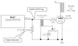
The attenuator is not a solution, it's a PROBLEM...Don't do it.
Cheers,
What do you think about this possible solution ?
The attenuator is not a solution, it's a PROBLEM...Don't do it.
Cheers,
May I jump in?
Hello,
I have a question about the tube SRPP output stage posted in this page, which is designed by Thorsten.
In the Vasfda article is discussed the value of the I/V resistor for the TDA1541, which cannot withstand the common mode voltage of a 270 Ohm resistor.
However a 100 Ohm figure is given as a maximum value for the PCM63, saying that similar limitations apply to the 1541 also.
Looking in the other threads I noticed that for this DAC are suggested values between 20 and 50 Ohm.
Doesn't using such a small resistor bring to a much lower output level? Is there a way to compensate for this?
I'm quite new in the tube world, so bear with me.
Cheers
Andrea
- Status
- This old topic is closed. If you want to reopen this topic, contact a moderator using the "Report Post" button.
- Home
- Source & Line
- Digital Source
- DIY tube output in DAC - needs advice...