The price to pay for freedom is allowing others to have the same amount of freedom.
I do, KBK can present anything he wants. I think there is a sentiment that certain arguments should be handicapped in some way because they have some kind of "unfair advantage" due to general acceptance. Too bad, crap is crap.
Ken, I appreciate your kind and generous thoughts.
How are your sales going?
You are welcome. More than one person has thanked me for stating the obvious.
"I've not come for what you hoped to do. I've come for what you did." - V for Vendetta
Hello Ken,
I planed to see that film tonight. It seems there is no hazard, perhaps a common vibration....
Very fine..."I've not come for what you hoped to do. I've come for what you did." - V for Vendetta
I planed to see that film tonight. It seems there is no hazard, perhaps a common vibration....
Return to the center of the discussion
Hello bettersimple,
V = 4.5VRMS
F = 7.83Hz
L = 50mH
R = 140 ohm
I = 4.5V / 140 ohm = 32mA (current in the inductor)
P = Z x I² = 2 x Pi x 7.83 x (50*10-3) x (32*10-3)² = 2.54mW
The power emitted by the coil is near 2.54mW.
Wahou!
There is an error on my first evaluation!
Hello bettersimple,
I use a reduced formula to evaluate the power emitted bay the coil....I currently use an LM6172 dual opamp to generate a 4,5Vrms sine (about 40mA) feeding a 50mH air inductor; the resistive load is about 140ohm....
V = 4.5VRMS
F = 7.83Hz
L = 50mH
R = 140 ohm
I = 4.5V / 140 ohm = 32mA (current in the inductor)
P = Z x I² = 2 x Pi x 7.83 x (50*10-3) x (32*10-3)² = 2.54mW
The power emitted by the coil is near 2.54mW.
Wahou!
There is an error on my first evaluation!
This gives 197µV x 3.33mA => 656nWI'm using a 1.2mH inductor with 600 ohm serial resistor powered by 2V RMS.
This gives 3.33mA in 1.2mH inductor => 197µW. (no!, only 197µV)
Last edited:
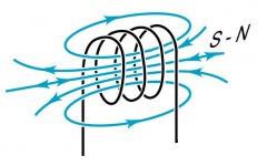
I obtain best results when the center of the coil is horizontal, and, particularly when the center of the coil follow the North-South orientation....One important thing: I take the coil in the vertical plane so I can see this big "O" just in front of me.
The other devices I know have an internal antenna placed in the horizontal plane, do you think I used it in a wrong way?...
Attachments
Thanks Eric,
I'll test the orizontal orientation.
By the way, when I'll have other time to invest I'll try to design an oscillator using an xr2206 and a buffer.
I never wasted much time in snake oil, I used to experiment with non oversampling dacs, asynch reclocking, usb-i2s interfaces, LDR volume attenuators, nelson pass projects, tubes, but this thing is so weird and effective and so cheap to try...
Maybe I'm highly suggestible, because in the past I heard differences darkening cd borders and changing the PSU cables, things that make engineers laugh.
OK guys, here is my humble 2 cents on schumann generators. I have been experimenting and studying various ways of enchancing listening experience by affecting the listener, in last 6 years, because I realized that the listener's state of mind, his perception has tremendous effect on the whole "musical experience". Schumann generators was one of the many techs I have tried, and I found it pretty solid and worth trying.
First of all, it is really surprising that people try to evaluate them by switching on and off and listening. Do they really believe that schumann generators would affect the gear? That's pretty nonsense. You can NOT evaluate schumans by turning it on and off and comparing sound, because it is not a gear that generator affects, but the listener, and it takes time for listener to ajust after switching it on\off. Change the perception and the whole sound and musical experience will change, but it has nothing to do with the gear.
Now, back to generators. I have been using AR device for several months now, and I like what I get. I have as well made a "portable" version, that can be used locally in 2 ways - either by direct electric brain stimulation via electrodes (so-called "transcranial brain stimulation"), or by applying magnetic coils to various places of your head. Electrical stimulation is much more profound, but I don't like it in terms of musical experience, however, it can calm you down in about 20 minutes from even the most severe "bad mood" like hystery etc.
The very clearly noticeable and positive effect I am getting in tems of AUDIO is from using portable schumann generator with a couple of magnetic coils (I am using "telephone pick up coils" that I bought together with Shakti Magnetic Brain Stimulator) placed on both temporal lobes. In about 20 minutes you start feeling very focused and at the same time relaxed, and can focus on music - your perception becomes a magnifying glass and you can really immerse into the musical event, sometimes very deep. Uisng it more than 30 minutes, however, seem to worthen the effect, maybe it is "too much", I dunno. So, it is probably worth switching it off after 30 minutes or so, and enjoying the achieved state.
Here is the diagram of Tiny-based high precision square wave generator I have been using. It was kindly developed for me by John Ullasman, and his help in building it is very much appreciated. As well, I am attaching (see attached ZIP file below) a software for 7.83 hz version (originally, it was intended to generate 77.4 hz for classical Transcranial Electric Brain Stimulation that is very good too, but for other things, not audio. In the above original file at John's web site, you can find 77.4 hz software).
Oh, by the way, one of interesting observation about AR ghenerator. It has been constantly ON in last 7 or 8 months, during my wife's pregnancy, then I removed it when I had an apartment renovation. Now my child is 1.5 months old and as many babies he is having kolicks and not very good night sleep with short naps and lots of wake ups. 3 days ago I thought - hey, when he was in womb, he was used to constant schumann influence, what if I turn it on again? Which I did. Surprisingly, after that he is having much much better night sleep, overally more calm and much less kolicky. I dunno if this is a result of getting "back" to what he is used during pregnancy (i.e. constant schumann waves) or as a result of overal generator's centering and calming effect. Anyway it is positive experience.")
First of all, it is really surprising that people try to evaluate them by switching on and off and listening. Do they really believe that schumann generators would affect the gear? That's pretty nonsense. You can NOT evaluate schumans by turning it on and off and comparing sound, because it is not a gear that generator affects, but the listener, and it takes time for listener to ajust after switching it on\off. Change the perception and the whole sound and musical experience will change, but it has nothing to do with the gear.
Now, back to generators. I have been using AR device for several months now, and I like what I get. I have as well made a "portable" version, that can be used locally in 2 ways - either by direct electric brain stimulation via electrodes (so-called "transcranial brain stimulation"), or by applying magnetic coils to various places of your head. Electrical stimulation is much more profound, but I don't like it in terms of musical experience, however, it can calm you down in about 20 minutes from even the most severe "bad mood" like hystery etc.
The very clearly noticeable and positive effect I am getting in tems of AUDIO is from using portable schumann generator with a couple of magnetic coils (I am using "telephone pick up coils" that I bought together with Shakti Magnetic Brain Stimulator) placed on both temporal lobes. In about 20 minutes you start feeling very focused and at the same time relaxed, and can focus on music - your perception becomes a magnifying glass and you can really immerse into the musical event, sometimes very deep. Uisng it more than 30 minutes, however, seem to worthen the effect, maybe it is "too much", I dunno. So, it is probably worth switching it off after 30 minutes or so, and enjoying the achieved state.
Here is the diagram of Tiny-based high precision square wave generator I have been using. It was kindly developed for me by John Ullasman, and his help in building it is very much appreciated. As well, I am attaching (see attached ZIP file below) a software for 7.83 hz version (originally, it was intended to generate 77.4 hz for classical Transcranial Electric Brain Stimulation that is very good too, but for other things, not audio. In the above original file at John's web site, you can find 77.4 hz software).
Oh, by the way, one of interesting observation about AR ghenerator. It has been constantly ON in last 7 or 8 months, during my wife's pregnancy, then I removed it when I had an apartment renovation. Now my child is 1.5 months old and as many babies he is having kolicks and not very good night sleep with short naps and lots of wake ups. 3 days ago I thought - hey, when he was in womb, he was used to constant schumann influence, what if I turn it on again? Which I did. Surprisingly, after that he is having much much better night sleep, overally more calm and much less kolicky. I dunno if this is a result of getting "back" to what he is used during pregnancy (i.e. constant schumann waves) or as a result of overal generator's centering and calming effect. Anyway it is positive experience.
Attachments
I tried making a simple 555 generator according to the basic schematics but it is very finicky or I am doing something wrong.What I see is that I can regulate it to 7.83 hz -although it varies between 7.81-7.86-but it is very sensitive to power supply and load changes so that if you connect a different load it will change quite a few hertz.Also connecting it to a cancelling coil or transformer there is no way of regulating the squarewave at exactly 7.83because you cannot see it on any normal measuring equipment.Plus it seems to overload i.e. 500 ma at 12v on a normal cancelling coil /tx which should present an infinite impedance right?
Hi protos,
Don't you try to put a buffer between NE555 and your coil?...Also connecting it to a canceling coil or transformer there is no way of regulating the square wave at exactly 7.83 because you cannot see it on any normal measuring equipment...
Well, I guess it is the next stage.But since Allen mentioned that the 555 can drive the coil directly I tried it this way.Actually it can drive the coil at a low power supply voltage around 6V and with a capacitor for any dc where the current on my supply shows around 150 ma.I just thought driving a bifilar coil there would be minimal current draw since the load presents a near infinite impedance at the frequency.I do not understand it. Obviously loading the output with a series resistor would mean that the voltage over the coil would go way down since it is only like 1 ohm.I wonder what Allen's set up is? Allen?Hi protos,
Don't you try to put a buffer between NE555 and your coil?
Also the 555 schematics do not mention that F is dependent on load/current.It is just an equation of R and C.
OK it works better with a simple mosfet follower.
However the current is too high.
The coil has maybe 1 ohm resistance and I am using a square wave of a couple of volts.This means that the output is quite few watts.
So I see the transistor needs a good heatsink.
Unless ofcourse I pad down the output to a few hundred millivolts.
What is the voltage on the other circuits mentioned previously eg kbk etc?
Can Allen please respond on this?
Are we talking millivolts here for the output or is there something I am missing such as cancellation?
RightSo in fact the voltage over the coil is minimal, right?
If we assume the impedance in the coili s no more than 1 ohm or thereabouts then it forms a divider with 560 ohms bringing the voltage to around 4mV over the coil, correct?
And yet it works for you it seems.
So I put a 33r in series and the voltage over the coil is 100mv.
I tested it on my main system and it works as planned.
Just one thing about this is that you cannot A/B immediately.You have to wait a minute or two before you play a track again in order to "absorb" or "detune" in respect of the waves otherwise quick a/b will confuse you.
However once you settle in the effect is almost amazing. Everything is wetter , more natural sounding , bigger and more coherent.
Good evening everyone, I was literally devouring this topic as I decided to build my own resonator and have extensively searched the internet already.
I guess I would go with the AR schematics but could someone indicate parts and values on it? Also, I would draw a spiral coil on PCB instead of squares with the same "circles" count as on AR.
Alternatively, could someone suggest a good and stable oscillator project which has already been tried and tested in this particular application from your own experience?
Finally,what is the desired emitting power level?
Thank you.
Last edited:
ne 555 basic application schematic tuned for 7.83hz , 12v, mosfet follower into anti-parallel secondaries transformer with about 10,000uf for the dc.
The higher voltage translates into a bigger effect.
If you limit the output with a resistor then it is not the same.Maybe lower voltage is ok for health and sleep in long term mode but for music I find the highest is better.
I have made three and I am beta testing with members of the ACA audiophile club here.
Interesting video...
HI People!
I'm an audiophile and I'm very attracted from your interesting posts about the Schumann Resonator.Here there is a video that confirms at 7.83 Hz happens something special:Marcos Dancing Magnets
The toroidal coil is pulsed with a progressive square wave,mantaining the same ampltude of the signal at each frequency.Note when the signal reach the center frequency of 7.8 hz, the oscillation of the donut magnets are at maximum and diminuish when you go out of phase. Really cool!
Some pages ago, was posted a schematic of the Audio Revive RR-77.If someone is so gentle to PM the missing values of the parts,it will be greatly appreciated.Thank you!
- Status
- This old topic is closed. If you want to reopen this topic, contact a moderator using the "Report Post" button.
- Home
- Design & Build
- Construction Tips
- DIY Schumann resonator?