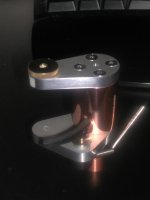
The copper dimpled drilled disc is the uppermost piece. It is what bears the knotted string. Below that will be the mu-metal pole piece sitting directly on top of the armtube magnet.
In the lower magnet holder will be the magnet and directly below the bottom magnet will be the lower pole piece between the magnet and the holder itself.
I posted a couple of links to some q&a that addressed what and how pole pieces in similar applications are up to, which seem to show what the function is in "manipulating" and containing the magnetic flux.
If need be I can double down the mu-metal discs, but that would place the knot to high. As it is the disc is about an rch more than 20% of the thickness of the magnet I'm using.
In looking at the patent drawings, it appears that the magnets are not encapsulated and such is not called out in the body of the text, only describe as highly pearmeable pole pieces. The drawings only depict them as discs directly above the top magnet and directly below the bottom. The drawing shows the top pole piece to be dimpled and drilled for the string...so I'll assume that Frank is not using mu-metal, but rather the C37 or soft iron he mentioned earlier as that material can probably be worked in such a fasion.
JD
Hi Jeff,
Your tooling has me green with envy. And a great score you made with the sample piece. A good size for allkindza stuff. But I wonder if you have thought out carefully what the pole pieces are really up to. As I see it from your descriptions your mu-metal pole piece is a simple flat disk of highly permeable ferrous metal a mere forty thousandths of an inch thick. It is positioned on the downlooking face of the magnet mounted in the arm. You have another small disk of copper between the mu-metal and the magnet. the copper disk is drilled/punched to provide the dimple for the suspension thread.
There have been some good links to explanations of pole pieces and their function in magnetic circuits in this forum recently. Now my question to you (and perhaps to me as well) is what is the function of a thin piece of flat mu-metal the same diameter as the magnet in this magnetic circuit? As I see it, it will allow the magnetic lines of force to pass virtually undistorted and unattenuated from one magnet to the other. It will make the effective surface of the magnet displaced from the true surface by the thickness of the pole piece. But that is the only function I can think of. Earlier discussion here dealt with the shaping of the pole piece(s) with respect to stability of the arm. Shapes such as barrel and domed and flat were all mentioned and if I remember correctly have been used by Frank Schroeder himself at one time or another. Now mu-metal can effect the effective short circuiting of a magnetic field. It is used all the time in magnetic shielding of transformers. In fact it is or has been common for shielding pickup cartridges. But to be effective it must enclose the object to be shielded. Even then there is some flux leakage through the mu-metal. There is no infinite attenuation. In fact the prime function is to provide a return path for the lines of force rather than stopping them dead.
So please think this through a bit more and come up with your interpretation of what the mu-metal disks are doing. I may very well be overlooking something which should be obvious. BTW you are very correct in not wanting to cold work the mu-metal. That hardens it and alters its high permeability parameter. After cold working it would need to be re-annealed which iirc is a difficult heat treating process.
So lets hear from you with your take on it.
Bill
Last edited:
Hi Jeff,
The patent drawings just show two ways of executing that type of bearing, neither of which is representative of how it's done in the Reference arms. The second drawing(which seems to be what you're trying to mimic) is close to how the No.2 arms are built.
@Bill
Flat cylindrical polepieces of ample thickness(avoid saturation!) will increase the attraction/flux line density on the opposite side by a factor of ~1.3
By using a different layout, this factor can be increased to 7.5 for circular magnets and 18(!) for flat, rectangular magnets.
I'll be of to the RMAF in Denver Monday, so soon I won't be able to reply for about three weeks(sorry).
Have fun guys,
Frank
Another further note nin reading the wording of the patent.. It says the bottom magnet "may" be potted to increase the flux density between the two magnets and that if used that way, the magnets need to be perfectly aligned to avoid vtf differences....
in describing figure 2 drawing...
quote...
"A pole piece 16 made out of a high permeability material yields a magnetic shielding effects in relation to the area below the lower magnet 14, while increasing flux line density in the gap between the two permanent magnets 13 anf 14. Flux line density can be increased further by "potting" the lower permanent magnet 14. The permanent magnet then needs to be centered perfectly, otherwise any asymmetry of the flux line distribution around this "bearing" will result in variations of the vertical tracking force (VTF) - as "seen" by the cartridge - along/across the usable radis of the record" unqutoe
Further on in the description it goes on to say an alternat method of supprting the arm by drilling the upper polepiece and countersinking the hole so the knot does not interfere with the polepiece and the magnet. There is no verbage at all about "potting" the upper magnet.
So my read is that a partially encapsulated bottom magnet is "optional" and that option will increase the (laymans term) attraction of the two magnets by focusing the field to a smaller area... BUT they have to be aligned to create an even field else it effects the vtf.
There is no specific callout for the thickness of the pole pieces, either disc or potting "can". I went with 20% based on one of the links I read, but I'm doing a little more research to see if this is an appropriate value.
As far as fabricating a bottom "pot" as opposed to just a "disc", may take more resources that I can find... maybe using just a disc will yield most of the benefits of an increase of magnetic strength without much of the worry of "perfect" alingnment of the top and bottom magnet..... ah but close enough is only good for horseshoes and nuclear warfare ;^P
JD
another note...
Just found some soft iron rods 13mm dia. I can have it sliced and machined to yield a "pot" for the bottom magnet. No need to worry about cold working this material. THis should give me a wall thickness of about .0684"
Maybe just center drilling and cutting a piece the height of the magnet and using my mu-metal disc for the bottom.... ah but thinking aloud.... leakage...
probably best to just make the "pot" entirely out of the soft iron and machine a hole with a flat bottom to recieve the magnet leaving only the face of the magnet (facing the armtube magnet) the only exposed surface.
Then I'll design the bottom aluminum pice to accomadate the "pot assembly"
that's the ticket.......")
JD
Just found some soft iron rods 13mm dia. I can have it sliced and machined to yield a "pot" for the bottom magnet. No need to worry about cold working this material. THis should give me a wall thickness of about .0684"
Maybe just center drilling and cutting a piece the height of the magnet and using my mu-metal disc for the bottom.... ah but thinking aloud.... leakage...
probably best to just make the "pot" entirely out of the soft iron and machine a hole with a flat bottom to recieve the magnet leaving only the face of the magnet (facing the armtube magnet) the only exposed surface.
Then I'll design the bottom aluminum pice to accomadate the "pot assembly"
that's the ticket.......
JD
another interesting article, I just may pop the $22. to download
http://jjap.ipap.jp/link?JJAP/14/1511/
JD
http://jjap.ipap.jp/link?JJAP/14/1511/
JD
found some potted neo magnets..
looks like they may be good for the bottom magnet?
http://www.strongmag.com/ndfeb_pot.cfm
looks like they may be good for the bottom magnet?
http://www.strongmag.com/ndfeb_pot.cfm
Jeff,
What is the status ? Any progress with the pole pieces ? I am planning to build the arm wand & base section this weekend. Following are the details I am have in mind. Please let me know your opinions/suggestions:
1. Wood wand will be of ebony/teak - 12 mm diameter with 5 mm hole. Will be damped using danish oil/linseed oil.
2. Rear end of the wand will be of aluminium alloy - 10 mm diameter.
3. The wooden wand section and the aluminium section will be encapsulated in a brass tube - 12 mm diameter (Do we need aluminium here) ? The top magnet will be placed inside this tube.
4. Head shell plate will be of aluminium - 2mm thickness.
5. The top and bottom plates will be of brass.
6. The arm base post will be of ebony/teak - 30mm diameter.
7. The magnets will be of neodymium with 10mm in diameter with 5 mm in thickness.
Please correct me if I am wrong...
Best regards,
Bins.
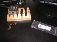
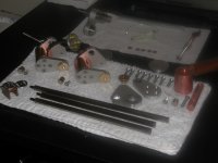
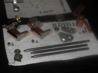
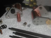
Parts are coming in a little at a time. Some parts have as much as 30 working days lead time. Here's a pic of the accumulation so far. Notice one of the lower support has a built in arm rest.
As I mentioned in an earlier post, farming the pieces out was a bit pricey for one-offs, so for about $50 more I can build 3 complete arms....
Jeff Davison
As I mentioned in an earlier post, farming the pieces out was a bit pricey for one-offs, so for about $50 more I can build 3 complete arms....
Jeff Davison
Attachments
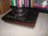
my schroeder wannabe... well almost, still some teaking to do.
had some time the past couple weeks so I decided to make my first tonearm. Still needs a bit of work but its a good start and it seems that it should work at the very least. Now I just need to finish my turntable
cheers
matthew
had some time the past couple weeks so I decided to make my first tonearm. Still needs a bit of work but its a good start and it seems that it should work at the very least. Now I just need to finish my turntable
cheers
matthew
Attachments
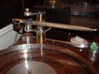
its just a nine inch arm. The wire is gonna be cardas wire as soon as it arrives in the mail.
I still have some issues i need to sort out. the rear aluminium arm tube must of moved when I milled it cause the magnet base is a little tilted. So i will remake that piece. at least that was one of the easiest pieces.
other then that i am pleased so far, and cant wait to have up and playing!
I still have some issues i need to sort out. the rear aluminium arm tube must of moved when I milled it cause the magnet base is a little tilted. So i will remake that piece. at least that was one of the easiest pieces.
other then that i am pleased so far, and cant wait to have up and playing!
Hi,
@Matthew: Are you using a tube for the rear piece ? As per my knowledge, the rod will produce have eddy currents that a tube. So, I am little confused. What is the wood made of and what is the arm diameter ? I am planning for a 10 inch arm of ebony.
@JD: How is the counter weight mass calculated ?
Regards,
Bins.
Hi,
Please check the link for knowing about the use of pole pieces: Dexter Magnetic Technologies
Best regards,
Bins.
Please check the link for knowing about the use of pole pieces: Dexter Magnetic Technologies
Best regards,
Bins.
Hi,
Got my tonearm cable yesterday. It is a 36 AWG cable of 1 meter length. The cable will be provided with RCA pins for directly plugging it into the phono preamplifier. I have a few questions regarding the tonearm cable usage:
1. Do we need to twist the cable in pairs (How many twists are required per inch ) ?
2. What is the required diameter for a standard cartridge clip ? I am having some crimp connectors with me. It can take wire of value from 24 AWG to 28 AWG. Can I use them as the cartridge clips ?
3. Where is the ground cable terminal attached to ( Is it to the aluminium tubing or is it to the aluminium plate used to hold the cartridge )?
Best regards,
Bins.
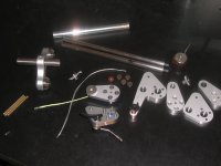
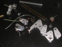
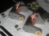
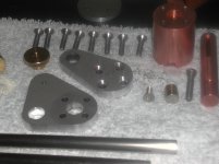
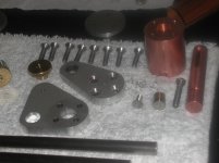
More parts coming in and enough to build up, fit and finish / polish the partial assemblies. One is disasembled for viewing.
I'm building these 3 for myself. One for a Garrarard 401 project and the other 2 for future tables. It was an incremental cost for 3 over 1. Biggest cost was the setup charges for the parts, the piece part price was fairly low. Two of the arms will have a 10.5 inch spindle to pivot distance and the other is a 12 inch.. And NO, they are not for sale, so please don't ask. The drawings are definately not available either.
Jeff Davison
Attachments
Last edited:
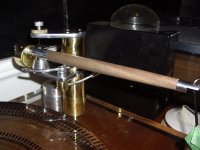
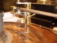
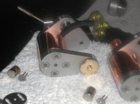
a couple more shots. THe main body is copper, and the armtubes are titanium with an inner tube of carbon fiber suspended / damped with about 10 evenly spaced buna-n "o"rings.
Still waiting for the armtube parts, base, and for the bottom magnet housing.
Jeff Davison
Still waiting for the armtube parts, base, and for the bottom magnet housing.
Jeff Davison
Attachments
Last edited:
- Home
- Source & Line
- Analogue Source
- DIY Schroeder Tonearm???