Additions
Hello,
IRF510 works fine for me. But I was told by fa-schmidt at HeadWize that Toshiba counterpart of IRF513 (Thus low power MOSFET. IRF510 is pretty high power ... medium scale.)
I was a little skeptical at first, but after fa-schmidt giving me a completely review, I feel it might be worth a shot. Besides these cost like couple dollars unlike 300B.
Don't get all caught up in DC coupled design. Recently there are reports that if DC coupled version give off pretty powerful DC offset at turn on and off that persist for over few secs. Unless the output has DC offset correction, I am no longer confident as to its safty. (AC design isn't all that bad, I enjoyed for quite a while before upgrading my system.)
You should use good PSU, but I don't think using massive amount (over 10,000uF) is a good idea. You should feel some fear simply by thinking about that much capacitance. It almost always means trouble if not careful.
With 10,000uF, your amp should operate WITHOUT power for nearly 1 min. I say that is enough. Use sophisticated paralleling of somewhat small ceramic and several other caps for optimum effect. That is more important that maxing out caps. (I think you all agree to that if you are building a headphone amp.)
Tomo
Be careful about Your Headphones
I agree with you Tomo.
Headphones are very easy to burn,
compared to Loudspeakers.
So you have to be careful not using a construction
that is putting out DC-offset too long.
I would like to recommend AUDIO OSCON (solid electrolyt).
They are much better, and will have longer life, than any wet electrolyte
like them Black Gate or what they all are called.
Put several in parallell, if you have low impedance Headphones,
and you want a low cutoff frequency.
If you are a very rich man, use Parallelled Polypropylene.
That is the ultimate way.
I say, you will not lose anything in sound
if you use that solution at output.
Jean said:
Question , how exactly does one calculate how big of a heatsink I would need for LM317 with 25 volts going IN and 15 out ?
25 - 15 = 10V drop across LM317
At a current draw of say 1A, gives around 10W of heat dissipation from the LM317.
My split rail double layer PCB (LM317 & LM337 regulation):
An externally hosted image should be here but it was not working when we last tested it.
fame at last
Well, the "BAM headphone buffer" would have split rails and, unlike the direct-coupled design G posted, it would use an output cap between FET and headphones and thus eliminate all of the input parts aside from the potentiometer. It would use a CCS to load the FET.
The sound would be better still if a pair of bipolars were used instead, say in CFB configuration. Bipolars are considerably more linear in this application.
"have you got z design for a bipolar transistor based amp?
one that wouldn't be much more complicated than the Szekeres?"
http://sound.westhost.com/project70.htm
See ya,
Tim.
one that wouldn't be much more complicated than the Szekeres?"
http://sound.westhost.com/project70.htm
See ya,
Tim.
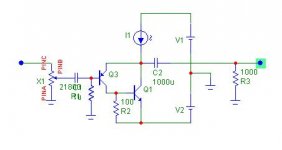
Here's a bipolar design. I've just acquired this schematic capture software so I'm not too good with it yet.
Most part values are the same as in your original circuit. Voltages are +/- 10V to 15V as before. The Current source is 500mA. Driver transistor pnp ZTX753 or similar, output npn MJE243 or similar. base to gnd resistor at pnp is 22k. You need psu caps from both rails to ground too (not shown).
That's it. It'll sound sweet as a nut.
BAM
Attachments
Re: Additions
Can you tell me more about this toshiba mosfet fa-schmidt told you?
Tomo said:Hello,
IRF510 works fine for me. But I was told by fa-schmidt at HeadWize that Toshiba counterpart of IRF513 (Thus low power MOSFET. IRF510 is pretty high power ... medium scale.)
I was a little skeptical at first, but after fa-schmidt giving me a completely review, I feel it might be worth a shot. Besides these cost like couple dollars unlike 300B.
Tomo
Can you tell me more about this toshiba mosfet fa-schmidt told you?
Hello,
Originally, this amp was design for semi-newbies to get into the world of intermediate audio amp builders. That is probably the reason the auther of the original article, Mr Szkeres, decided to use MOSFETs instead of BJT. Unlike BJTs, MOSFETs does not draw current so biasing is ultra easy. Also, notice the matching in rather unnecessary. This is very unlike BJT counterpart. (Not that I hate BJT or anything.)
I think you will find that the amp works quite well. CCS will improve the linearity, but difference is barely audible. I see no reason to hustle about. This is, however, only true if you need about 1V swing. So it is more than satisfactory with Grado headphones. However, for headpones like K240M which require about 2~3V swing might give you unsatisfied feelings.
Tomo
P.S. I am sorry, I don't remember the exact mosfet. But it might be 2SK214.
This mosfet is not IRF510 equivalent, it is more closer to IRF513.
"Unlike BJTs, MOSFETs does not draw current so biasing is ultra easy"
Seems to me they both need a single resistor for bias, and the FET needs a VHF damping resistor to keep it stable. In either case you get a dc offset - usually several times higher with the FET because of Vgs. FET is good when you need very high input resistance and you don't care about the higher input capacitance, lower output resistance and non-linearity.
"Also, notice the matching is rather unnecessary. This is very unlike BJT counterpart."
I couldn't disagree more. What do you mean exactly?
In any case, this design does not require matching as it is single-ended.
For this configuration I recommend the lastest technology - BJT. Did you know that FETs were invented first?
I've sent a mail to pcb-designs (who made the shematic of the ZenV4 PS I want to adapt to a szkeres)
This is the mail I sent:
"Hi
I've found your site on diyaudio.com
The PS you built seem to be very good ones! Great job!
I'm working on a heaphone amp, the shematics are done for it
But I'm still looking for a goos power supply
Can you help me?
All infos can be found on this topic:
http://www.diyaudio.com/forums/showthread.php?s=&threadid=7505&perpage=15&pagenumber=1
As you can see, i'm working a modified version of your ZenV4 PS. But I'm still not sure for the values to be used, especially for the self.
If you can tell me what values you think good for the capacitors and the self, it would help me much
Thanks
Bricolo"
And there is his answear:
"Hello Mr.Bricolo,
Don't use the Zen-4 power supply.
It is unregulated.
Try to use double regulated power supply with the combination of the PI filter.
Use 3,9 mH - 6,8 mH Air Core inductors.
The capacitors don't requires high voltage rating, so you can use those
with lower voltages, like 25 VDC or so.
The high capacity of the capacitors is desireable.
If I can be of further assistance to you, please feel welcome to contact me
again.
Best regards,
Kristijan Kljucaric
http://web.vip.hr/pcb-design.vip"
Why does he say that his ZenV4 PS is unregulated?
An externally hosted image should be here but it was not working when we last tested it.
This is the mail I sent:
"Hi
I've found your site on diyaudio.com
The PS you built seem to be very good ones! Great job!
I'm working on a heaphone amp, the shematics are done for it
But I'm still looking for a goos power supply
Can you help me?
All infos can be found on this topic:
http://www.diyaudio.com/forums/showthread.php?s=&threadid=7505&perpage=15&pagenumber=1
As you can see, i'm working a modified version of your ZenV4 PS. But I'm still not sure for the values to be used, especially for the self.
If you can tell me what values you think good for the capacitors and the self, it would help me much
Thanks
Bricolo"
And there is his answear:
"Hello Mr.Bricolo,
Don't use the Zen-4 power supply.
It is unregulated.
Try to use double regulated power supply with the combination of the PI filter.
Use 3,9 mH - 6,8 mH Air Core inductors.
The capacitors don't requires high voltage rating, so you can use those
with lower voltages, like 25 VDC or so.
The high capacity of the capacitors is desireable.
If I can be of further assistance to you, please feel welcome to contact me
again.
Best regards,
Kristijan Kljucaric
http://web.vip.hr/pcb-design.vip"
Why does he say that his ZenV4 PS is unregulated?
Bricolo,
I think you asked if anyone had built the Elliott DoZ amps? Pictures here:
http://photos.yahoo.com/sidneycharles
Background here:
http://www4.head-fi.org/forums/showthread.php?threadid=8443
I think you asked if anyone had built the Elliott DoZ amps? Pictures here:
http://photos.yahoo.com/sidneycharles
Background here:
http://www4.head-fi.org/forums/showthread.php?threadid=8443
sidney: your work look very clean!
I like the way you made the second DOZ (the one with speakers)
The grill on the top is a far better solution than plexy
Even if it isn't as good as a closed piece of metal, for eletromagnetic interferences insulation, it is very good
I like this
But the DOZ is too complicated for me, for a first project
I want to build something very simple, before building a zen with speakers
any amp for single supply can be used with split supply
if you use negative as ground.
As long as toal voltage is not to high for the amp.
if you read the posts in this and other threads you will find schematics with GZekeres adopted for split supply
this designs comes in 2 categories
one with capacitor output, safest and most simple
another with DC-output
this incorporates an adjustment for DC-output offset adjust
Why don't you use "Search" keyword: gzekeres
you will find a lot of split supply schematics
I could make a search for you
but I am lazy and I imagine you know how to search
Happy Listening!
Can't find it
Tried it. Got one hit. Oh, wait, there's two hits now.halojoy said:Why don't you use "Search" keyword: gzekeres
you will find a lot of split supply schematics
- Status
- This old topic is closed. If you want to reopen this topic, contact a moderator using the "Report Post" button.
- Home
- Amplifiers
- Headphone Systems
- DIY Power supply for a Szekeres headphone amp