Neutrik NLT8FX Speakon STX 8 Pole Female Cable Connector Nickel Housing
I've used these for many years. Rugged connectors that make a very good electrical contact. Up to 8 poles in one connector. There are male and female versions.
I've used these for many years. Rugged connectors that make a very good electrical contact. Up to 8 poles in one connector. There are male and female versions.
Today's frustration was that I downloaded a demo version of Arta software to try out for speaker testing. It's PC-only, which I knew, but what I lost track of is the fact that my audio system, as it stands at the moment, accepts only digital inputs. The only PC I have at home is a Surface Pro 3 which only has one usb port and a displayport. There's no TOSLINK included in the headphone jack as there is in the Macbook Pro I've been using for my measurements so far.
I think REW will run on almost anything as it is JAVA based.
It is pretty close in capabilities to ARTA. Not exactly but close at least.
I have REW running on both the PC and Mac but I wanted to try some of Arta's convenient features. For example, it makes much more convenient the process of taking a sequence of measurements and averaging them. Its graphics capabilities are also more flexible (and attractive, as a bonus). But Arta costs money and if it turns out it's going to require new hardware as well, I may have to give it a pass. I'm still exploring possibilities. I found a ridiculously cheap Behringer usb soundcard with TOSLINK output but it lacks phantom power and a few other features.
Few
Few
I decided I need a usb hub anyway, so I ended up buying a cheapo Behringer usb audio interface because it was the cheapest way I could find to get usb-in and TOSLINK-out. Seems crazy but it was less than $30 US so I'll see if I can get the combination to work...
My repaired amp did NOT arrive today as promised but at least the connectors from Parts Express did arrive so I can spend some time tomorrow seeing if I can get meaningful impedance measurements. We're supposed to get 21" of snow tomorrow so I'll have some time on my hands. I'll post results if I end up with something credible.
Few
My repaired amp did NOT arrive today as promised
but at least the connectors from Parts Express did arrive so I can spend some time tomorrow seeing if I can get meaningful impedance measurements. We're supposed to get 21" of snow tomorrow so I'll have some time on my hands. I'll post results if I end up with something credible.Few
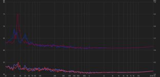
For the impedance fans I'm attaching three images:
1) Impedance measurements of the left and right planar magnetic midranges and tweeters. The two upper traces (higher impedance) are the midranges and the two lower traces are the tweeters. In both cases red lines correspond to the right hand speaker. I applied 1/48 octave smoothing to retain the wiggles but remove the whiskers.
As I mentioned several posts ago I know there are some diaphragm tension gremlins (wrinkles) in both speakers. Presumably their responsible for the differences between the impedance peaks down in the 35 Hz range. It's worth noting that I roll off the planar drivers below 200 Hz so there's very little electrical drive at 35 Hz. Those resonances could be driven acoustically by the neighboring woofer array, though.
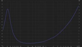
2) Impedance measurement of the left woofer array. The fundamental resonance is at 31 Hz, and the impedance there maxes out at about 16 ohms. The right woofer measurement is extremely similar but I ended up with about a 1 ohm positive offset that I didn't catch until after I had disassembled the measurement rig. I'll have to double-check and make sure I don't have a faulty connection as a result of the new speaker connections I described recently.
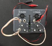
3) On the off chance someone else has a similar audio interface I'm including a photo of my cobbled together impedance measuring rig. There's a 99.4 ohm metal film resistor at the right input; that's the sense resistor. The red and black leads go to the speaker terminals.
The good news is that the FedEx guy beat the worst of the blizzard to my house so my (hopefully fully repaired) amp is now back onsite. If all goes smoothly I'll be back into music by this evening.
Few
1) Impedance measurements of the left and right planar magnetic midranges and tweeters. The two upper traces (higher impedance) are the midranges and the two lower traces are the tweeters. In both cases red lines correspond to the right hand speaker. I applied 1/48 octave smoothing to retain the wiggles but remove the whiskers.
As I mentioned several posts ago I know there are some diaphragm tension gremlins (wrinkles) in both speakers. Presumably their responsible for the differences between the impedance peaks down in the 35 Hz range. It's worth noting that I roll off the planar drivers below 200 Hz so there's very little electrical drive at 35 Hz. Those resonances could be driven acoustically by the neighboring woofer array, though.
2) Impedance measurement of the left woofer array. The fundamental resonance is at 31 Hz, and the impedance there maxes out at about 16 ohms. The right woofer measurement is extremely similar but I ended up with about a 1 ohm positive offset that I didn't catch until after I had disassembled the measurement rig. I'll have to double-check and make sure I don't have a faulty connection as a result of the new speaker connections I described recently.
3) On the off chance someone else has a similar audio interface I'm including a photo of my cobbled together impedance measuring rig. There's a 99.4 ohm metal film resistor at the right input; that's the sense resistor. The red and black leads go to the speaker terminals.
The good news is that the FedEx guy beat the worst of the blizzard to my house so my (hopefully fully repaired) amp is now back onsite. If all goes smoothly I'll be back into music by this evening.
Few
Attachments
Concerning the wiggles and whiskers…I’m wondering if this is a byproduct of using the swept sine signal for the impedance measurement of a transducer. It may be completely unrelated to swept sine and more just a function of your measurement setup. Did you happen to measure a 4ohm resistor as a comparison to see if the wiggles and whiskers are still present?…I applied 1/48 octave smoothing to retain the wiggles but remove the whiskers.
Some comments on the use of swept sine signal for impedance measurements:
ARTA-Post#296
ARTA-Post#298
ARTA-Post#168
I'm thinking that the middle picture is the impedance graph. Those wiggles would be a lot easier to decipher if we had a phase graph along with it. When they line up you can see what is happening in the electrical domain and in the time time domain. Frequency rounds out the whole spectrum. There is method to this madness.
Thanks for the impedance discussion links. I'll read them through. I got distracted from impedance measurements when my "repaired" amp was finally returned and I then found that not only was it not repaired, it's now worse than before I sent it in. So my attention has been on making the system work with an old amp whose gain doesn't match the one it's replacing and which doesn't like load impedance loads. Not what I want to be working on...
I don't think I saved my resistor impedance measurements so I'll have to take another look. I used a 100 ohm resistor and headphone output for the measurements so I assumed the 4 ohm impedance of the planars was just too small compared to 100 ohms to yield a clean measurement. I was going to try again with a smaller resistor.
While I haven't yet tested Arta I think I have successfully pieced together a way to use my one-usb-port and no-TOSLINK-out Surface Pro for measurements. That should allow me to give Arta a try (I've been using a Mac so far and Arta won't run on it without complications I don't want to deal with).
By the way, both the first and second attachments on post #286 are impedance measurements. As explained in that post, the first attachment is for the planars (left and right midrange, and left and right tweeter). The second attachment shows one of the woofer towers.
Few
Bummer on the buggered up amplifier. That has to be disappointing.
So graph number one is the planar impedance! Something is a little funny there. You should not have all those wiggles and waggles. Your woofer stack impedance was pretty normal looking. But there are a bunch of wiggles there to.
Have you done a loop back sanity check on your outboard sound card?
So graph number one is the planar impedance! Something is a little funny there. You should not have all those wiggles and waggles. Your woofer stack impedance was pretty normal looking. But there are a bunch of wiggles there to.
Have you done a loop back sanity check on your outboard sound card?
I'll make another run at the impedance measurements including a check on a known-value resistor. The planar and woofer measurements were done in exactly the same way, one right after the other. You'll have to be a little more specific about what you mean by "loop back sanity check" in this impedance testing context.
Few
Few
According to FedEx tracking the new amplifier should be here Friday. I hope it just plain works, with no surprises.
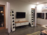
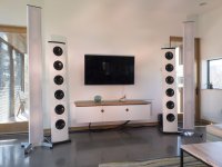
While waiting for it I completed the cabinet that hides the electronics and is intended to "tie the room together." (That's a Big Lubowski movie quote, in case it isn't obvious.) It's actually supposed to tie the room and speakers together (round woofers, round cabinet handles...get it?) but I couldn't find a quote that accommodated speakers. The old amp below the cabinet is the temporary one keeping me in music until the new class D amp shows up. Things should look tidier once the amp is gone and the extra cable mess is eliminated.
I realize the diyaudio crowd isn't likely to be overly interested in room decor but I'm sort of dead in the water until my electronics are back in order and since you asked for an update, I'm posting a crappy compressed iphone photo as project life support. I do appreciate the expression of interest!
Few
Attachments
Thanks Mark. I appreciate the supportive comments. As usual, construction took longer than planned/expected. Is that part of the definition of "project?" It seems to be in my experience. I think I hold the title of world's slowest painter of cabinetry. I swear I sand off more than I apply. On the other hand, the top slab of cherry was hand-planed and I'm pretty pleased with the result. My wife gets credit for the idea of hanging the cabinet on the wall rather than using legs.
Few
Few
I'm not sure how many readers are familiar with this site on diy audio projects. It makes for fun browsing. My towers just got added to the mix.
By the way, the new amplifier has arrived, is installed, and seems to work without glitches. Hooray! That allowed me to get the limp-along amp off the floor and neaten the set-up a bit. Pardon the mod lighting---I was fiddling around in photo-land a bit today and got "creative" toward the end of the session. The photos on the homebuilthifi site are more straight-shootin'.
Few
Attachments

- Home
- Loudspeakers
- Planars & Exotics
- DIY planar magnetic + open baffle woofer array