One way to see how much effect the baffle is having as far as delaying the back wave from diffracting around it is to look at a sonogram of the polar data. With no/minimal baffle around the planar you will see a smooth transition from HF directivitity regime to LF dipole regime. As the baffle gets larger you will notice a bloom in off-axis response indicating the work of the secondary sources at the baffle edge diffraction. Attached example plots came from these threads:...I think my last paragraph gets too close to conflating the diffraction that happens at the edge of a dipole with finite width baffle and the reflections that could arise from projections (or cavities) encountered by the sound as it moves away from the diaphragm. I believe frequency response ripples I've seen below 1 KHz have mostly been the result of interference between the out-of-phase back wave sound diffracting around the baffle and interfering with the front wave sound at the mic.
http://www.diyaudio.com/forums/plan...r-graebener-plus-markaudio-2.html#post4488916
http://www.diyaudio.com/forums/plan...-tweeter-reductio-ad-minimum.html#post4407603
Depending on how reflective your side walls are, you may find you need to adjust EQ to remove a glare to the sound if your speakers have significant off-axis bloom. This should show up in your MMM, just something to be aware of if you are trying to track down the "why".
Very cool impulse visualization in post#179 btw.
")
Attachments
Thanks for the suggestion, Bolserst. I'll have to see if I can massage the data to produce some version of the directivity plots you showed.
Glad you liked the impulse visualization. I had to do a couple of handsprings to get something that was close to what I was envisioning. If I could automate the data acquisition and file saving part it would only take a few minutes to make such measurements and display the results.
Few
Glad you liked the impulse visualization. I had to do a couple of handsprings to get something that was close to what I was envisioning. If I could automate the data acquisition and file saving part it would only take a few minutes to make such measurements and display the results.
Few
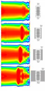
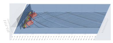
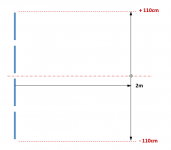
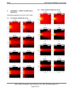
Since I have had a couple private inquiries about how gaps between the planars result in the criss-cross patterns seen in Few’s plot in post#170 I figured I’d post a few pics to help visualize what is going on. I calculated impulse response @2m from the planar array from just above to just below the ends of the array. As before, negative heights are used for response below the array center, positive heights for response above the center.
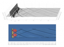
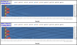
Attachment #2: A pair of contour plots of the impulse response for the array in free space, and with the first floor and ceiling mirror included. X-axis is time, Y-axis is height. Comparing the two, it is easy to see what time ranges of the impulse responses are coming from the direct sources and what time ranges are coming from the mirrors. Note that the ceiling mirror arrives later in time than the floor mirror since the gap to the ceiling is larger. (660mm vs 170mm)
Attachment #3, #4: If I trim up and appropriately scale the contour plot with mirrors(and flip it so floor is at top) it can be directly compared with plot from post#170. Skewing the contour plot to match the perspective of post#170 and the overlay makes the pattern match even more obvious. It's not a perfect match, but pretty darn close
To understand why the pattern is generated in the matrix of impulse response, lets look at a couple in more detail.
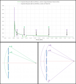
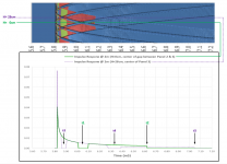
Attachment #5: Here are the impulse responses for the middle of the array and middle of the 3rd panel. To improve clarity, I used monopole sources with response to DC rather than dipole sources. Note the smoothly decaying impulse interrupted with a few notches and a level shift.
Attachment #6: Thinking of the impulse as a time history of the acoustic energy arriving from the line array. You can draw a circle of radius = (time x speed of sound) to see where the energy is coming from at the point on the impulse. When you do this, you will notice the notches align with times when this radius falls on gaps in the array. The shift down in level of the purple curve relative to the green curve just after t4 is because the time window has moved beyond the top of the array for the purple curve and acoustic energy is only being received from the single bottom panel of the array.
Any slice through the contour plots of Attachment #2 can be investigated in a similar manner to understand that the pattern is generated due to shifted time windows between the mic and the gaps in the array or gaps between array and floor/ceiling mirrors.
Attachment #2: A pair of contour plots of the impulse response for the array in free space, and with the first floor and ceiling mirror included. X-axis is time, Y-axis is height. Comparing the two, it is easy to see what time ranges of the impulse responses are coming from the direct sources and what time ranges are coming from the mirrors. Note that the ceiling mirror arrives later in time than the floor mirror since the gap to the ceiling is larger. (660mm vs 170mm)
Attachment #3, #4: If I trim up and appropriately scale the contour plot with mirrors(and flip it so floor is at top) it can be directly compared with plot from post#170. Skewing the contour plot to match the perspective of post#170 and the overlay makes the pattern match even more obvious. It's not a perfect match, but pretty darn close
To understand why the pattern is generated in the matrix of impulse response, lets look at a couple in more detail.
Attachment #5: Here are the impulse responses for the middle of the array and middle of the 3rd panel. To improve clarity, I used monopole sources with response to DC rather than dipole sources. Note the smoothly decaying impulse interrupted with a few notches and a level shift.
Attachment #6: Thinking of the impulse as a time history of the acoustic energy arriving from the line array. You can draw a circle of radius = (time x speed of sound) to see where the energy is coming from at the point on the impulse. When you do this, you will notice the notches align with times when this radius falls on gaps in the array. The shift down in level of the purple curve relative to the green curve just after t4 is because the time window has moved beyond the top of the array for the purple curve and acoustic energy is only being received from the single bottom panel of the array.
Any slice through the contour plots of Attachment #2 can be investigated in a similar manner to understand that the pattern is generated due to shifted time windows between the mic and the gaps in the array or gaps between array and floor/ceiling mirrors.
Attachments
-
 Gap_impulse_response_timing.png100.5 KB · Views: 66
 -
 Gap_impulse_response_comparison.png293.8 KB · Views: 71
 -
 Gap_theory-vs-measured_overlay.png139.7 KB · Views: 75
 -
 Gap_theory-vs-measured_compare.png311.4 KB · Views: 178
 -
 Gap_response_vs_time-vs-height.png501.9 KB · Views: 175
 -
 Gap_simulation_layout.png4.7 KB · Views: 174
Last edited:
In your experience, how late in the impulse response should reflections be considered as part of the “first arrival” signal that would have the peaks and dips EQd out? Usually with large planar dipoles I don’t see any significant contribution from reflections in the first 5mS – 7mS. This may be because these type of loudspeakers tend to be placed well out into the room and away from sidewalls.The left/right variations are recommended to sort out reflections from planes parallel to the arrays. Due to their vertical size they "average out" a lot of in room objects in a room, except for large vertical parallel planes.
It would be good to take a close look at the IR to see the level of reflections left after the averaging process.
Bolserst: The match between my measurements and your model is quite remarkable. Very cool to see. Thanks for putting in the effort! I confess that I'm relieved that my (second) explanation of the ripples is supported by your model.
How hard would it be to add to your model a tapered or attenuated response at the ends of each panel? I was envisioning putting felt over the top and bottom inch or two of each panel (an unsophisticated variation on what RAAL does with their ribbon tweeter). I'm guessing the ripples would be less pronounced but it would be interesting to know if there's any hope of this technique working before trying to find felt and figuring out how to install it. Of course if adding it to the model isn't a quick job please don't take it on. You've been overly generous with your time already.
Few
If you pursue this type of attenuation you will end up introducing a comb filtering effect in between each panel.
A goal of 7 ms reflection free would be very beneficial for imaging. Personally I tried to get the first 20 ms as clean as I could. Meaning I tried to get the reflections down as far as I could using absorption panels. My Eq was done after that. But I only used a single measurement position. Using a summed multi measurement would get the reflections out of the IR too. But the listening position would still have that added sound (not as bad a thing as most assume). Our minds are great to filter out the room, so I do have great hope this can be percieved to sound very good. As long as the tonal balance is about right. Which is percieved over a longer time frame than imaging queues. More in line with what we measure with a MMM measurement.In your experience, how late in the impulse response should reflections be considered as part of the “first arrival” signal that would have the peaks and dips EQd out? Usually with large planar dipoles I don’t see any significant contribution from reflections in the first 5mS – 7mS. This may be because these type of loudspeakers tend to be placed well out into the room and away from sidewalls.
My goals were different. I wanted to obtain a "you are there" type of presentation. Let the queues in the song tell you what the space "looks" like. To get that you need something that works with the room. Arrays and horns are the types of speakers I can think of that can do that without having to turn a living room into a studio. Each with their own strengths and weaknesses.
A goal of 7 ms reflection free would be very beneficial for imaging. Personally I tried to get the first 20 ms as clean as I could. Meaning I tried to get the reflections down as far as I could using absorption panels. My Eq was done after that. But I only used a single measurement position. Using a summed multi measurement would get the reflections out of the IR too. But the listening position would still have that added sound (not as bad a thing as most assume). Our minds are great to filter out the room, so I do have great hope this can be percieved to sound very good. As long as the tonal balance is about right. Which is percieved over a longer time frame than imaging queues. More in line with what we measure with a MMM measurement.
My goals were different. I wanted to obtain a "you are there" type of presentation. Let the queues in the song tell you what the space "looks" like. To get that you need something that works with the room. Arrays and horns are the types of speakers I can think of that can do that without having to turn a living room into a studio. Each with their own strengths and weaknesses.
Intriguing comments.
Were the recordings that you are using as a reference popular music?
I do a fair bit of work listening to recordings and their inherent sound differences. Most if not all popular music is not recorded in a true stereo setup. The vast majority are done using single point mono mic pickups that are turned into a pseudo stereo. When you hear the difference between a true two mic recording and one done the mono method it is very noticeable.
"If you pursue this type of attenuation you will end up introducing a comb filtering effect in between each panel."
Hi Mark,
Thanks for the continued interest!
Actually, the comb filtering is already there, with the abrupt gaps in place. My question is whether the clear ripples in the time domain, and comb filtering in the frequency domain, would be less intrusive if the transition from radiating diaphragm to non-radiating diaphragm could be made less abrupt.
The fourier transform of a gaussian is a gaussian--smooth in one domain is smooth in the other domain. So I'm wondering whether smoothing the radiation as a function of z (the long dimension of the towers) would lead to a smoother response as a function of vertical angle (altitude) in front of the speakers.
That's how it works in optics and it seems to me this situation is completely analogous. A sharp iris in optics yields pronounced diffraction rings. A smooth gaussian cross-section in place of the iris yields transmission that varies smoothly with angle.
So my question is whether the frequency domain comb filtering (and the time domain ripples) can be made less intrusive by smoothing the radiation in the spatial domain.
Few
You will find in actual practice that distance from the plane of emission is your best friend in listening to a stack of drivers.
As you have the distances set up now the comb filtering effects will be based around 6 to 8 kilohertz, or at least close to that area by simple edge to edge calculations. All the measurements you do will eventually lead to your having to make decisions. And the placement and type of measurements you pursue can either inform or misinform your decisions.
Looking at the wealth of measurement work you have accomplished and their correlation to the simulations done as well leads me to push for you to listen and adjust according to well known sound sources. I think I mentioned this quite a few posts ago.
You have more than a handle on what your speakers are doing. You have little to gain in pursuing more measurements. Now's the time to sit back play some stuff and gently adjust to suit the best reproduction of sounds and instruments that you are very familiar with. Your wife's voice over a pickup via your measurement mic is a great standard to work with. Your aural memory will guide you to the right settings if you are gentle on the EQ. Between 1 kilohertz and 4 kilohertz you are in a region that a db or so at the right point can make some interesting differences in perspective of a sound. Literally move the apparent sound stage closer or farther. Peaks are more a problem than gradual dips. If you can have an A and B setting. Original with no tweaking and B tweaked. Best done over a period of days. Little by little. Everyone has a geewhizz effect that what ever they are involved in sound wise starts to become better and better very quickly. SOmetimes the following day will tell you different.
This is as much a study in psychoacoustics as it is in meteorology. I would say that you have nailed the measurements. And try as I might I have never been able to take a set of measurements and directly apply them to a contouring of a loudspeaker system in a mathematical exacting method. The measurements are indicators. Pointers as it were.
Use your ears man! They are what is going to be the final arbiter in this system in the end anyway.
Intriguing comments.
Were the recordings that you are using as a reference popular music?
I do a fair bit of work listening to recordings and their inherent sound differences. Most if not all popular music is not recorded in a true stereo setup. The vast majority are done using single point mono mic pickups that are turned into a pseudo stereo. When you hear the difference between a true two mic recording and one done the mono method it is very noticeable.
I make it a point not to listen to a single genre to get an idea what I am listening to, system wise. Of course I hear differences between the different techniques. Though that has little to do with getting my own room out of the way.
Here's a picture, as measured at the listening position showing my room. There's still reflections visible, but they are attenuated quite a bit.

It also shows the timing I was after to get me close to my ideal.
There's more I do to maximise my listening enjoyment. That part has to do with Stereo's inherent cross talk, the sound of the left speaker entering the right ear and vice versa.
All of it was done with measurements though, but I didn't forget to listen. Measurements and theory are my guide, long listening sessions over several weeks and with a variety of music tells me if something works or is worthwhile to pursue. It's easy to be impressed for a couple of hours. It's a lot harder to keep that feeling over a longer run of time.
This 20 ms with suppressed reflection level isn't new, I just imitated that from basic studio knowledge. Even though there are different views within that world too.
My thread has quite a few reviews linked in the first post:
http://www.diyaudio.com/forums/full-range/242171-making-two-towers-25-driver-full-range-line-array.html
To me they mean more than my own words. I build it and adjusted it, making me pretty biased. I basically measure everything, though I've had my ears measured by an outside party
. Know what you are listening to is my advice. Don't assume, measure. The true Art is in the music.Thanks for the advice Mark. I'm in this game to have fun, and part of the fun for me comes from learning some new tricks, pushing the envelope of what I know or understand. So some of my activities very likely look, to many thread readers, like unnecessary distractions from the job of getting the speakers into final form. But I embarked on this project not just to end up with speakers to listen to. I also wanted them to be test beds for some ideas I had. Trying to visualize the waveform radiated by the planar towers, for example, is part of my effort to determine whether my ideas have any merit. I've certainly learned a lot along the way.
So I've been posting the results of some of my off-track activities on the off chance someone here finds them interesting or useful. It also makes it feel less silly to spend hours making measurements and graphs if I share them. I don't really know if they're of interest to many but for now I'll blindly keep plugging.
I certainly agree listening is a key component to the process of voicing the speakers. I've been doing that along the way. It just takes me awhile to log enough hours with enough kinds of music and styles of recording to come to any useful conclusions. For that reason I've been keeping constant the equalization scheme I use when listening to music. I think I'm concluding I need to drop the bass level a bit. I can then focus my attention on the question of what the level between 800 and 8000 Hz should be. Different measurement techniques (moving mic, averaging first arrivals, etc.) yield different answers to that question and I'll need some gut sense of what sounds right to inform my interpretations of the graphs.
Few
Something tells me you put lot more time and effort into your measurements than I did at the computer keyboard. There are many aspects of theory built into my modeling tools that I have yet to validate with experimental results…and I only have so much free time. So, a heartfelt thanks back at you for expending the effort to meticulously collect the set of 58 spatially distributed measurements.Bolserst: The match between my measurements and your model is quite remarkable. Very cool to see. Thanks for putting in the effort!
If you are talking about level shading, I’m already setup to do that with any definition you can come up with. There is some merit to the idea as you can see in the attached image from Keele’s paper on line sources. http://www.xlrtechs.com/dbkeele.com...rmance Ranking of Loudspeaker Line Arrays.pdfHow hard would it be to add to your model a tapered or attenuated response at the ends of each panel? I was envisioning putting felt over the top and bottom inch or two of each panel (an unsophisticated variation on what RAAL does with their ribbon tweeter). I'm guessing the ripples would be less pronounced but it would be interesting to know if there's any hope of this technique working before trying to find felt and figuring out how to install it.
I’ve never applied it to individual planars in an array, just the whole array. So, may have to run that in the next couple of days to see what the results are for a few common windows functions. (ie Hanning, Hamming, Triangle, Tukey). Obviously no matter what the result, you would be losing considerable sensitivity.
If you are talking about frequency shading where you are progressively rolling off the highs as you move toward the top and bottom of the planar, I am not currently setup to do this, but wouldn’t take much effect. However, I would expect this technique to increase vertical dispersion for each planar which would increase the comb filtering effect as mwmkravchenko mentioned. In any case, if you can define areas and roll-off characteristics, I can easily include it in the model.
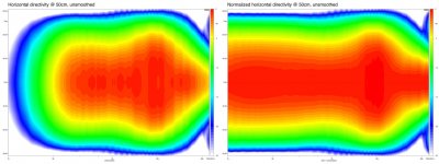
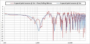
Just want to make sure we are talking about the same effect. Comb filtering results from difference in path length from two sources(or more). With center-to-center distance of roughly 57cm and measuring at 2m, the first null would occur between 1kHz and 2kHz (depending on the height) where the path length difference is ½ wavelength. If you replaced the planars with 4 point sources located at the center of the planars you would get a response something like the attached, illustrating the comb filter issue. With the planars uniformly driven along their height, their vertical directivity precludes comb filtering to this degree....As you have the distances set up now the comb filtering effects will be based around 6 to 8 kilohertz, or at least close to that area by simple edge to edge calculations.
+1...Between 1 kilohertz and 4 kilohertz you are in a region that a db or so at the right point can make some interesting differences in perspective of a sound. Literally move the apparent sound stage closer or farther...
Attachments
Bolserst: I wasn't thinking of shading in the Keele sense, more along the lines you described next--slightly attenuating the output (primarily at higher frequencies) for the top and bottom few cm of each panel. I follow your (and Mark's) argument about increasing the vertical spread from each planar because its effective length is reduced, and the increasing the comb filtering. So I guess the question is whether it would also "soften" the ripples seen in the impulse responses as I suggested. If it does both, then does this result in better or worse sound quality? Clearly perfection in the time and frequency domains go hand in hand. When imperfections are inevitable it's less clear to me how they can be best hidden.
Of course what I'm suggesting may just make things worse in all domains, including the "effort required to implement" domain. It wouldn't be the first time...
Few
Of course what I'm suggesting may just make things worse in all domains, including the "effort required to implement" domain. It wouldn't be the first time...
Few
If you use floor to ceiling, think of what happens with the floor and ceiling reflection of that shaded array.
The funny thing I see in the Keely array papers is; his CBT is presented with a floor reflection helping out the concept, while somehow the straight array and the shaded array don't seem to get that beneficial reflection from the floor nor the ceiling. I can't figure out why he left that part out?
The funny thing I see in the Keely array papers is; his CBT is presented with a floor reflection helping out the concept, while somehow the straight array and the shaded array don't seem to get that beneficial reflection from the floor nor the ceiling. I can't figure out why he left that part out?
I have never investigated it. It looks like Hann-shading at both top and bottom would come close to eliminating floor and ceiling reflections for all but the lowest frequencies. I am curious though...will try to give it a look this weekend.If you use floor to ceiling, think of what happens with the floor and ceiling reflection of that shaded array.
You might check this paper out for direct comparison of point source, straight line(unshaded/shaded) and CBT all with floor reflection. (no ceiling though)The funny thing I see in the Keely array papers is; his CBT is presented with a floor reflection helping out the concept, while somehow the straight array and the shaded array don't seem to get that beneficial reflection from the floor nor the ceiling.
http://www.xlrtechs.com/dbkeele.com/PDF/Keele (2005-10 AES Preprint) - CBT Paper 5.pdf
Conveniently made only 1.25 m tall, so barely up to listening lengths...
I wonder why.
Yes, I've seen that one before, a flawed presentation just like the previous attempts. If the CBT was all that, wouldn't we be seeing a lot of copies after all this time? I like the new Lexicon concept way better. Look at what happens at floor level with the straight array. Once you make it floor to ceiling that's what you get in the middle of the room. I don't believe in short arrays or wasting efficiency in a flawed concept.
If I didn't know any better one would think he had something to sell.
Few, instead of moving to shading, why not try and equalize the summed average to see what it really does. I noticed you were looking at the IR, do keep in mind that IR is just a representation of what's happening and mostly shows high frequency material above 8 KHz in that standard representation. EQ that sum and look at what that does for your IR. Also try the filtered IR tab and use those 1/3 octave filters to see what happens at those frequencies. Switch back to the IR and compare it to a Dirac pulse with the same filters.
Then look at early waterfall plots and see how clean a ridge you can get.
You have an almost seamless source, no need for any shading at all. Concentrate on the best way to EQ, then rerun the tests to see the variations that remain. I don't think you'll be disappointed.
Your room does more harm than your speakers right now.
I wonder why
.Yes, I've seen that one before, a flawed presentation just like the previous attempts. If the CBT was all that, wouldn't we be seeing a lot of copies after all this time? I like the new Lexicon concept way better. Look at what happens at floor level with the straight array. Once you make it floor to ceiling that's what you get in the middle of the room. I don't believe in short arrays or wasting efficiency in a flawed concept.
If I didn't know any better one would think he had something to sell.
Few, instead of moving to shading, why not try and equalize the summed average to see what it really does. I noticed you were looking at the IR, do keep in mind that IR is just a representation of what's happening and mostly shows high frequency material above 8 KHz in that standard representation. EQ that sum and look at what that does for your IR. Also try the filtered IR tab and use those 1/3 octave filters to see what happens at those frequencies. Switch back to the IR and compare it to a Dirac pulse with the same filters.
Then look at early waterfall plots and see how clean a ridge you can get.
You have an almost seamless source, no need for any shading at all. Concentrate on the best way to EQ, then rerun the tests to see the variations that remain. I don't think you'll be disappointed.
Your room does more harm than your speakers right now.
Last edited:
Before anyone gets the wrong idea, I'd call the short straight array a flawed concept. Not dissing the CBT. Though the CBT might have it's own set of problems if you move it into a reasonably sized room.
The one thing we as DIY audio lovers have going for us is to match our speakers to our room, creating something that works together.
The one thing we as DIY audio lovers have going for us is to match our speakers to our room, creating something that works together.
Just want to make sure we are talking about the same effect. Comb filtering results from difference in path length from two sources(or more). With center-to-center distance of roughly 57cm and measuring at 2m, the first null would occur between 1kHz and 2kHz (depending on the height) where the path length difference is ½ wavelength. If you replaced the planars with 4 point sources located at the center of the planars you would get a response something like the attached, illustrating the comb filter issue. With the planars uniformly driven along their height, their vertical directivity precludes comb filtering to this degree.
In the case of a planar the emissive area is pretty much the entire height of the diaphragm. So you are looking at edge to edge differences. Not center to center.
Yes, I've seen that one before, a flawed presentation just like the previous attempts. If the CBT was all that, wouldn't we be seeing a lot of copies after all this time? I like the new Lexicon concept way better. Look at what happens at floor level with the straight array. Once you make it floor to ceiling that's what you get in the middle of the room. I don't believe in short arrays or wasting efficiency in a flawed concept.
If I didn't know any better one would think he had something to sell.
A CBT type array does in deed work.
What you are witnessing in it's lack of acceptance, is more a situation of an industry and by extension the public's allergic reaction to change. It is amazing how entrenched the industry is when it comes to "new" product offerings. And how much the cost of a product is liked to it's ever seeing the light of day in terms of being made available to the public in the first place. That's why for instance I'm currently working on a CBT and will be offering them for people that are interested in a no holds barred type of implementation. I have had a few email discussions with Don Keele about the ideas behind it's best form and function.
The fact is that the most striking simulations were done with an array construction that has not been made available publicly. And constructing it is not so easy.
CBT - Kravchenko-Audio
Did that one a few years ago.
I liked your thread wesayso. And your choice of construction method is a whole lot of work. My hats off to your tenacity. I really liked the creative use of templates. The moment I saw your first picture I thought, a perfect situation for doing this at home with the right templates, and voila a little farther down sure enough you did indeed use them.
- Home
- Loudspeakers
- Planars & Exotics
- DIY planar magnetic + open baffle woofer array