A thin layer of glue doesn't "break" the magnetic circuit.
Yeah, you can segment the curve as long as each row of magnets share the same pole piece.
Yeah, you can segment the curve as long as each row of magnets share the same pole piece.
Nice!
Apart from having to redesign it into smaller parts it might make it easier to manifacture. Since each segment is flat I won't have to curve which was something I was somewhat fearful of. I could also probably use the same dimensions of steel plate on the top and the bottom since I can fill in the gaps with the plastic parts. That would let me increase or decrease xmax or all the other dimensions without having to get new steel plates.
Assuming 7 cm wide plates:
7 rows 50x3x3 magnets
5 rows 50x3x3 magnets
3 rows 40x5x5 magnets
5 rows 12x5x3 magnets
5 rows 12x4x3 magnets
But because 12mm short segments might be overkill I might order 24mm long also / instead of 12mm long:
5 rows 24x5x3 magnets
5 rows 24x4x3 magnets
Since the main cost of laser cutting with fractory was the overhead I could probably order say 60cm of length of segments of each part for a reasonable price. Then I could play away with all the combinations and see what works best.
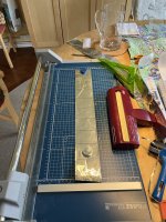
I bought the same corrugator you linked to in your thread @solhaga and it seems to work pretty well. It corrugates to roughly 1.5 mm peak to peak which is more than I'd like but by stretching the foil slightly I can turn it into 1 mm peak to peak. There is a risk, however, that the after-stretching will not be perfectly uniform so I might steam ahead with designing my own corrugaror. I bought some ball bearings with big enough inner diameter such that I can print the axles on my 3d printer without having to worry that it would snap.
I also learned that I will have to be careful when corrugating to ensure that it is corrugated perfectly parallel. I'll need to devise a technique to ensure that. One idea is to tape the membrane edge to a table and then stretch it while corrugating closer and closer to the taped edge. Or to build a feeding mechanism.
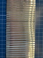
I also learned that I will need to property stretch the mylar before applying the aluminum foil. The membrane in the image looks like **** but it worked well enough to calculate how much length is lost from the corrugation.
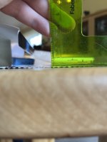
The black lines are 5 cm long. With a 1.5 mm peak-to-peak it got reduced to 4.4 cm, when I stretched the peaks to to 1 mm it is reduced to 4.6 cm.
I also learned that I will have to be careful when corrugating to ensure that it is corrugated perfectly parallel. I'll need to devise a technique to ensure that. One idea is to tape the membrane edge to a table and then stretch it while corrugating closer and closer to the taped edge. Or to build a feeding mechanism.
I also learned that I will need to property stretch the mylar before applying the aluminum foil. The membrane in the image looks like **** but it worked well enough to calculate how much length is lost from the corrugation.
The black lines are 5 cm long. With a 1.5 mm peak-to-peak it got reduced to 4.4 cm, when I stretched the peaks to to 1 mm it is reduced to 4.6 cm.
Attachments
Last edited:
Yes, I've noticed that skewness too. My idea is to have guides that ensures the membrane to be fed straight.
Or I'll make my own as you are planning to. Here's some inspiration.
But I wonder if the precison of the coggs along the whole length of the corrugator will be better than the Uchida corrugator.
Have you got the Silhouette Cameo 5 yet?
I had to send mine back, when unpacking I discovered that the adjustable right roller was broken:


Too bad as this is the USP of this cutter. Appearantly the black Cameo 5 doesn't suffer from this weakness.
I guess the properties of the plastics are different; always use black zip ties you know.
Or I'll make my own as you are planning to. Here's some inspiration.
But I wonder if the precison of the coggs along the whole length of the corrugator will be better than the Uchida corrugator.
Have you got the Silhouette Cameo 5 yet?
I had to send mine back, when unpacking I discovered that the adjustable right roller was broken:
Too bad as this is the USP of this cutter. Appearantly the black Cameo 5 doesn't suffer from this weakness.
I guess the properties of the plastics are different; always use black zip ties you know.
I just dismantled the corrugator. I carved away some debris on the cogg endings and lubricated it all with silicone spray.
So now it rolls smoother and possibly straigther.
The thing does not have bearings, it's plastic against plastic, so I don't except to be a long term solution anyway.
It'll be very hard to keep a straight feeding of the membrane, in my case it is 230 cm long, holding the corrugator with left hand and cranking it with the right.
But, I think the cogg rolls can be repurposed. They are sturdy enough with a steel tube inside them and I also think it'll be hard to 3D-print anything sturdier and precise.
This is a very good idea, by the way, this will allow you not only to adjust the radius of the convexity, but also to create a reverse-focused driver, experiment will show everythingYou can even adjust the curvature of the speaker motor if you make hinges that connects the segment.
 .
.- Home
- Loudspeakers
- Planars & Exotics
- DIY midtweeter planar, physically curved and shaded to be used in a dipole CBT