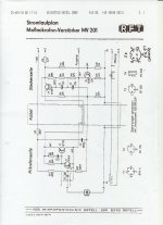
I just found this via Google. Phase splitter transistor... not exactly an instrumentation amp but, hey... it is what it is...
BTW, it seems that there are a few different versions. I don't know which one this is.
Thanks for that!
Yeah, nothing fancy there. C6 looks to be drawn in the wrong place
it goes to ground rather than the other side of R6 at the phase splitter output.
Outputs are in a sense open emitter to the phantom power source resistors.
I'd like to up C2, C3, C6 to 10 uF to flatten the response down to below 20 Hz.
This subject is covered here, somebody measured the mic and there is no output on one pin, it is not actually balanced and the connection of the coupling cap is as shown in the schematic - as much as it makes no sense:
ECM8000 microphone measuring techniques and usage discussion - Page 5 - Home Theater Systems - Electronics and Forum - HomeTheaterShack
I comment further here the phase splitter resistors seem to be set up incorrectly also:
ECM8000 microphone measuring techniques and usage discussion - Page 5 - Home Theater Systems - Electronics and Forum - HomeTheaterShack
ECM8000 microphone measuring techniques and usage discussion - Page 5 - Home Theater Systems - Electronics and Forum - HomeTheaterShack
I comment further here the phase splitter resistors seem to be set up incorrectly also:
ECM8000 microphone measuring techniques and usage discussion - Page 5 - Home Theater Systems - Electronics and Forum - HomeTheaterShack
Hi Alex,
Please see this link. Digikey have over 33000 in stock.
Digi-Key - P9925-ND (Manufacturer - WM-61A)
Regards
Peter
Please see this link. Digikey have over 33000 in stock.
Digi-Key - P9925-ND (Manufacturer - WM-61A)
Regards
Peter
What a great thread!
Been looking in to computer based measurement for DIY loudspeaker projects, it would be a great thing if I could plug a mic in to my mini-laptop and hook an amp to the audio-output and run some basic measurements on projects I do.
As I really don't do enough projects to justify putting too much money in to "proper" equipment, a cheap DIY solution is what I'm after.
Now, this is an interresting comparison I found! Microphone measurements and comparisons
After seeing this, I went and ordered a pair of WM-61 capsules off e-bay in order to build a the microphone described on the Linkwitz lab web-page.
From the price it is obvious that there will be limitations, but if the comparison in the link is anything to go by, this should still be very usefull for the happy amateur!
The greater uncertainty will probably be the performance of the buildt-in sound card of my Asus IEEE mini-laptop...
True!
Somehow, I didn't think about that! If I simply loop a test signal directly from the audio/ headphone output and back in to the mic input via some attenuation, well, then I'll soon enough se what the system performance is!
And whatever software I end up instaling is clever enough (haven't got a clue about which yet!) I might even be able to self calibrate / compensate accordingly. Wow, that would be neat!")
Thanks for nudging me in the right direction!
Somehow, I didn't think about that! If I simply loop a test signal directly from the audio/ headphone output and back in to the mic input via some attenuation, well, then I'll soon enough se what the system performance is!
And whatever software I end up instaling is clever enough (haven't got a clue about which yet!) I might even be able to self calibrate / compensate accordingly. Wow, that would be neat!
Thanks for nudging me in the right direction!
Hi Alex,
Please see this link. Digikey have over 33000 in stock.
Digi-Key - P9925-ND (Manufacturer - WM-61A)
Thanks Peter!
Cheers,
Alex
Well, just installed the free Holm Impulse software, and it ha a function for "self-calibration" of the sound card, great stuff!
Now all I need is the mic.
Im planning to do the Linkwitz mic with a Panasonic WM 61 capsule and use the calibration file generously provided by askbojesen. I can only hope that this calibration file is allso appliccable when th capsule is used with the linkwitz circuitry!
Now all I need is the mic.
Im planning to do the Linkwitz mic with a Panasonic WM 61 capsule and use the calibration file generously provided by askbojesen. I can only hope that this calibration file is allso appliccable when th capsule is used with the linkwitz circuitry!
This subject is covered here, somebody measured the mic and there is no output on one pin, it is not actually balanced and the connection of the coupling cap is as shown in the schematic - as much as it makes no sense:
ECM8000 microphone measuring techniques and usage discussion - Page 5 - Home Theater Systems - Electronics and Forum - HomeTheaterShack
I comment further here the phase splitter resistors seem to be set up incorrectly also:
ECM8000 microphone measuring techniques and usage discussion - Page 5 - Home Theater Systems - Electronics and Forum - HomeTheaterShack
My ECM8000 also only has output on one pin.
I just finished the Linkwitz circuit, but I can't seem to make it work with my line-in.
A couple things first:
1) I did not do the WM-61A mod;
2) I connected the capsule in the conventional method as shown here, but with a 10k resistor going to +9V (the 10k resistor in Linkwitz' circuit to the left of the input cap goes to +9V instead of -9V);
The preamp and mic seem to work when I use it as the input to a set of powered speakers, but when hooked up to line input it seems to be lacking gain.
I am not sure how to troubleshoot this circuit, any ideas?
Thanks,
BarryV
Thanks Barry!
No, no line level pre-amp, I just plug it straight in to the mic-input on my ASUS (the only audio input available by the way)
I included an adjustable damping pad on the mic in the form of a 10k log potentiometer.
Seems that leaving it to zero damping and turning down the mic input level on the laptop gives the least noise.
I'll see if I can get some pictures out, the whole thing ended up looking quite swoosh actually!
Uncalibrated, the panasonic capsules often have a rising response starting somewhere around 4k, then being up about 3dB by 10k. That is an important region. My mic also had a very broad, 1dB bump in the midrange. Probably important too.
Yes, but, if your crossing over at 1.5 - 2 Khz, then at least you can cover the crossover range. Certainly enough to design a crossover far superior to using an "off the shelf" prebuilt crossover (not designed for your particular drivers).
I've built several mics with the WM60AY and WM61A capsules. So far, I've used them just connected directly to my sound card, no power or preamp. I usually set the +20 db boost on in the Windows mixer Control Panel Applet...
I think the capsules I have are pretty good up to about 10 Khz or so.
Last edited:
- Status
- This old topic is closed. If you want to reopen this topic, contact a moderator using the "Report Post" button.
- Home
- Loudspeakers
- Multi-Way
- DIY measurement mic