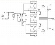
Now to improve efficiency we would need to adjust the main rail power supply. This also has the advantage of keeping the output transistors collector voltage close to constant.
We can do this with either a linear or switching method. The trick is where to insert the semiconductors. I show this with BJTs although if switching there are better choices.
We can do this with either a linear or switching method. The trick is where to insert the semiconductors. I show this with BJTs although if switching there are better choices.
Attachments

And then if you change the resistive feed from the +/-12v supplies for a pair of CCS..?
Edit: or one could simplify by keeping the resistive feed - but fed from a heavily-filtered 'tap' of the output rails, for simplicity (Chucking away c.50v allows a very large RC, or at least wide range of choice of R feed versus series I.R drop, surely)
Edit: or one could simplify by keeping the resistive feed - but fed from a heavily-filtered 'tap' of the output rails, for simplicity (Chucking away c.50v allows a very large RC, or at least wide range of choice of R feed versus series I.R drop, surely)
Last edited:
...D'oh. Its the end of a long week.
...logical extension would be: surely you could then make the two series feed resistors from +/-12v supplies into two pairs of series resistors fed from the output rails instead - and merely join the two 'centre-tap' junctions with a cap...
(I can't quite visualise the stability risk in my head right now, but it can't be too far awry if the cap is large enough)
Martin,
What happens if no loudspeaker is connected?")
The cost of the extra windings is just 60 turns on the toroid core. Although a separate transformer would give you a cleaner power supply feed particularly if you use a flatpack dual bobbin style.
As to a CCS you are getting it. Although what is being shown now is a maximum power amplifier the floating power supply has advantages in a very high performance design and has been sold as such. Personally I would use it with a single pair of output transistors for a 100 W+ amplifier.
ES
What happens if no loudspeaker is connected?
The cost of the extra windings is just 60 turns on the toroid core. Although a separate transformer would give you a cleaner power supply feed particularly if you use a flatpack dual bobbin style.
As to a CCS you are getting it. Although what is being shown now is a maximum power amplifier the floating power supply has advantages in a very high performance design and has been sold as such. Personally I would use it with a single pair of output transistors for a 100 W+ amplifier.
ES
Trick question! Since the AC line is fused at 20 amps a transformer much greater than 2400VA continuous rating is only of limited use! So how do you determine the intermittent transformer rating?
Now 65 volts at 120 volt input would give rails of 90 volts. The rating of our output transistors is 180 volts. So if we look at SOA we most likely will blow them up!
Even with 90 volt rails we only get 500 watts into 8 ohms, but 1000 watts into 4 ohms. The amplifier would be able to actually drive a 2 ohm load to just under 2000 watts as the transformer would begin to sag. (Or the power line!)
So if I have a 1000 real watt (power available for an 8 ohm loudspeaker's minimum impedance) amplifier how loud can it play before it will clip?
When doing live symphonic music there is a need for 30 db of head room. That would allow this amplifier to produce 1 watt average and with efficient full range loudspeakers of say 92 db @ 1 M. (There are lots of folks who will play pink noise and take a reading for a much higher number. That is because where you have a reproduction peak in response you get the most output. If you look at the output at the lowest frequency of interest fo home use you get a more meaningful number.)
Well the symphony on stage will run as high as 110 dba slow weighted. In the front rows about 95. So with a 1000 watt amplifier on recordings that are not compressed the amplifier is just adequate!
Now why would you want to reproduce a band at the same level as live? Well if you are familiar with at least the work of Fletcher & Munson you will understand that when you reproduce an instrument at a different volume, it actually sounds different!
Now if you are listening just to CD's then 20 db of dynamic range is probably enough. So you could use less efficient loudspeakers and still get realistic volume.
- Status
- This old topic is closed. If you want to reopen this topic, contact a moderator using the "Report Post" button.
- Home
- Amplifiers
- Solid State
- DIY Max Power Low Cost Amplifier Design