Hi Hugh, thanks for "imaginative": but I build different types of tonearms mainly to understand how they should work, trying to analyze, measure and document the results. For example, no comments on sound or other suggestive properties, not even with respect to any favorable judgments by others.
video - if you refer to those of the Lil Casey mk1 (# 2469-70) mk2 (# 2785 ---2833-2975), those at # 2501 and # 2906 - and the discussion in subsequent posts are still valid. I have been using the MK2 for months, changing the cables and improving the set up of both the parallelogram and the carriage, but it would not make sense to redo them for these imperceptible details -
If instead you refer to the measurements with the inverse pendulum (# 2574-2606 - # 2922 + discussion) there are just photos, a video would not make sense if it were not in slow motion, which I am not equipped to do.
See also the bending/compliance tests # 2615- 2891- 2911, by Niffy and me, and the subsequent in-depth discussion.
carlo
Jewell bearing. I found this moving testimony of what human beings can do by very simple means (it even looks like a full cycle process) - to remember when we diyers complain about our not enough sophisticated equipment.
Jewel Bearing - Based in Delhi, India, we are manufacturer and supplier of Jewel Bearings made of Glass, Sapphire, Ruby. Call +919810671836 for a Quotation
Jewel Bearing
carlo
.....I found this moving testimony of what human beings can do by very simple means (it even looks like a full cycle process) - to remember when we diyers complain about our not enough sophisticated equipment.
@ Carlo,
Thanks for the link.
Surprisingly, help 24hr / 24hr, 365d / 365d (and longer).
Chapeau for their resourcefulness.
Carlo (& Niffy), congrats with your achievements and field-tech-comments (& kis measurements)
Allez, salukes.
Karel
Hi all,
I've been having a conversation with Charles from truepoint in the UK about the availability of all the different components required for the jeweled bearing system. He can still supply all the components necessary and is willing to ship worldwide including Australia and the USA.
The prices are;
4 x P4 Pivots are £30.00 each, 8 x P4 Pivoots at £25.00 each.
4 x V-Jewels at £35.00 each, 8 x V-Jewels at £30.00 each.
2 x 4 mm dia' Silver steel Rods at £15.00 each.
Charles is going to get back to me with the price of tungsten carbide rods tomorrow.
The prices do not include postage.
Charles is contactable at: charles@true-point-audio.com
A full set of components will cost over £300. This is considerably more than using ballrace bearings but the performance is considerably higher too. You would be unlikely to be able to make an air bearing, including compressor and precision shaft, for anywhere near this price. The advantage of an air bearing is very low friction. From my videos you can see that friction is not an issue of any significance. My bearings have the advantage over an air bearing of offering superior mechanical grounding, not requiring a pump and costing less. Like air bearings this system will not suffer from bearing chatter. It is quite possible that this is actually a superior system.
Niffy
hi Karel: 24h, 365d, incredible; hoping that in leap years they will rest one day ...
But what they make is still more astonishing: milling the material, casting, cutting blanks, turning vee cups of few tenths, polishing, inserting with an old sewing machine...
But certainly the rubies, the emeralds, the diamonds made for the sultans, seen at the Topkapi were cut 1000 years ago with much less tools...
carlo
My bearings have the advantage over an air bearing of offering superior mechanical grounding, not requiring a pump and costing less. Like air bearings this system will not suffer from bearing chatter. It is quite possible that this is actually a superior system.
Niffy,
I have no doubt about the effectiveness of your jewel bearings. It is a very valuable contribution to the design of linear arm. I am sure some of the commercial arm builders will copy your idea soon or later.
Regarding mechanical grounding of a linear arm, if mechanical grounding refers to the transmission of vibration, air bearing has a built-in mechanism to deal with that. The thin air film between the bearing and shaft has a damping effect. New Way air bearing had demonstrated that feature. The damping generated by thin air film reduces the vibrations from cartridge movements and external vibrations from a turntable and other external sources. This may explain why the air-bearing arm is so quiet.
Jim
Hi Jim,
Mechanical grounding and damping are quite different though both can be beneficial.
Mechanical grounding provides a pathway for energy by rigidly coupling, in one or more of the six degrees of freedom, the carriage to the rail. 4 of the 6 degrees of freedom need to be coupled.
At low frequency the air gap in an air bearing couples the carriage to the rail quite well. The connection is rigid for 4 other 6 degrees of freedom. At high frequency the air gap forms a compliant, decoupling interface. The air in the gap does damps motion between the carriage and rail. The frequency at which the arm transitions from coupling to decoupling is dependent upon the size of the air gap and the air pressure. The smaller the gap and the higher the pressure the higher the transition frequency. This is why arms that use a closed bearing, like yours, sound better than the terminator open type bearing as the transition occurs at a higher frequency. In other words they couple for more of the audio band.
I have found that the more an arm is coupled the better it sounds. Virtually all of the most highly rated arms available commercially use spikes for their bearings, Swedish audio technology, Graham, kuzma, origin Live and continuum labs for instance. The spikes offering excellent coupling - mechanical grounding.
Niffy
Last edited:
I did the tests for two of my arms today.
YouTube
Total Mass of arm: 100 grams.
Koetsu Rosewood Signature, Low Compliance: 5x10⁻⁶cm/dyne at 100Hz
YouTube
Total mass of arm: 89 grams.
Benz LPs, Medium Compliance: 15 µm/mN
The tests made me think about the advantages and disadvantages of a linear arm comparing to a regular pivot arm again. For regular pivot arms, it is never a problem.
YouTube
Total Mass of arm: 100 grams.
Koetsu Rosewood Signature, Low Compliance: 5x10⁻⁶cm/dyne at 100Hz
YouTube
Total mass of arm: 89 grams.
Benz LPs, Medium Compliance: 15 µm/mN
The tests made me think about the advantages and disadvantages of a linear arm comparing to a regular pivot arm again. For regular pivot arms, it is never a problem.
Hi Jim,
I had to curtail my last post.
Regarding your point about the air gap acting to prevent external vibration from getting into the arm. The most problematic source of noise is that due to the stylus-groove interface. The only real way to reduce the amount of energy entering the arm from this source is to use a higher compliance cartridge. This would entail sacrificing your Koetsu Rosewood Signature which I'm guessing you don't want to do. Energy entering the arm from the other end will be due to motor noise, bearing noise (rumble) and ground borne environmental noise. All of these can be substantially reduced whereas the energy from the cartridge cannot. Hence in my opinion it is better to give the energy from the cartridge the cleanest path away from the arm.
Air bearings do have the advantage that external damping can be applied using viscous damping rather than the friction damping that I am using. Viscous damping is better.
I did say "It is quite possible that this is actually a superior system" not "quite probable"
Conventional pivoted arms will not necessarily result in lower cantilever defection than we have achieved. The antiskate mechanism is set to a fixed level but the actual skating force constantly varies. Pivoted arms still have lateral inertia there's just less of it.
The extra lateral mass of your arm might result in an extra 5-10arcminutes of misalignment (inaudible) but will result in over 10dB less movement of the cartridge body (very audible). And let's not forget that even a 12" arm is going to have tracking errors of up to a degree due to geometry. Also that 12" arm will have its fundamental bending mode probably 7 octaves lower in frequency than your arm with loads of harmonics in the audio band where you probably won't have any.
Niffy
Hi Niffy,
Actually, I am not sure why my air bearing arms are so quiet and have no explanation for that. What I said was only an educated guess. I have owned VPI and Graham 2.2. Comparing to these two arms, my air bearing arms are much quieter than these two arms to a large extent. I hardly clean my LPs.
I was not saying that conventional pivot arms are superior to linear arms. What I meant was that from designing aspects, it has this advantage because pivot arms have almost no friction both in vertical and lateral planes.
Jim
Regarding your point about the air gap acting to prevent external vibration from getting into the arm. The most problematic source of noise is that due to the stylus-groove interface. The only real way to reduce the amount of energy entering the arm from this source is to use a higher compliance cartridge. This would entail sacrificing your Koetsu Rosewood Signature which I'm guessing you don't want to do. Energy entering the arm from the other end will be due to motor noise, bearing noise (rumble) and ground borne environmental noise. All of these can be substantially reduced whereas the energy from the cartridge cannot. Hence in my opinion it is better to give the energy from the cartridge the cleanest path away from the arm.
Actually, I am not sure why my air bearing arms are so quiet and have no explanation for that. What I said was only an educated guess. I have owned VPI and Graham 2.2. Comparing to these two arms, my air bearing arms are much quieter than these two arms to a large extent. I hardly clean my LPs.
Conventional pivoted arms will not necessarily result in lower cantilever defection than we have achieved. The antiskate mechanism is set to a fixed level but the actual skating force constantly varies. Pivoted arms still have lateral inertia there's just less of it.
I was not saying that conventional pivot arms are superior to linear arms. What I meant was that from designing aspects, it has this advantage because pivot arms have almost no friction both in vertical and lateral planes.
Jim
Hi Jim,
I have a theory as to why your arm is so quiet.
A typical dust mote is in the range of 3-10um.
When the stylus is in the middle of the playing area (100mm from the center) the groove is traveling at 350mm/s relative to that stylus.
A typical stylus contact point with the groove wall is under 10um and the stylus at this contact point is less than 50um front to back, less with a fine line stylus. From when the stylus first hits the dust mote to when it is past it will be less than 50um even for a large dust mote. This will take 0.14mS.
The impact with the stylus will cause a single high level impulse. If you think of this impulse as half a cycle then 0.14uS is occurring at 3500hz. For small motes and fine line styluses this will occur at a higher frequency.
A single impulse at this frequency is not really audible.
What makes the impact audible is the system oscillating as it settles down. The oscillations will tend to occur at a lower frequency than the initial impulse very much like a bell ringing. In this case the bell is actually the tonearm. What you are actually hearing as surface noise isn't the dust itself but the ringing of your arm in response to the impacts. Have you ever noticed that higher quality arms seem to have higher frequency snap crackle and pop?
As your arm has a very high frequency, well damped fundamental resonance it doesn't ring very much at all so surface noise is less noticeable.
Just because you can't hear the dust doesn't mean that it isn't there. I would still recommend brushing each record both before and after playing in order to minimise stylus wear.
Niffy
Cat whisker test
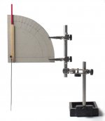
Disclaimer -- an extremely trivial test for LT frictions, not even asking for a simple rig like the reverse pendulum, or the rough set for a smartphone video, but unfortunately equally pitiless.
How to
First prepare your LT perfectly leveled, and with VTF = 0, so that the carriage can move at it's best. Now take a small 1x2x125 mm nylon cable tie, grab it vertically at one end and then gently push the other end on the head shell.
-- If the carriage moves almost without apparent bending (<<5°), congratulations, you may leave immediately these stupid toying.
-- if instead the cable tie flexes evidently (>>5°) sorry to inform you that it does with at least 2.0 - 3.0 mN - That cable tie was chosen because - imho- that friction is the maximum tolerable for a decent LT*.
For a better approach, build this "high tech rig" (attachment) and calibrate it on a VTF digital scale. (my test rig data: 5 ° = 2,5 mN -- 10 ° = 5,7 mN -- 15 ° = 9.8 mN -- 20 ° = 12,1 mN -- 25 ° =14,8 mN)
better than nothing - carlo
*to understand what we're dealing with: 200 mg is the weight of a 5x5 cm piece of office paper.
Attachments
Hi NIffy,
On my arms, all over the noise level seems much lower now.
I understand this. However, in most cases, I am too lazy.
Jim
Have you ever noticed that higher quality arms seem to have higher frequency snap crackle and pop?
On my arms, all over the noise level seems much lower now.
Just because you can't hear the dust doesn't mean that it isn't there. I would still recommend brushing each record both before and after playing in order to minimise stylus wear.
I understand this. However, in most cases, I am too lazy.
Jim
Hi Jim,
Like you I have very low levels of surface noise. What I meant when I said "Have you ever noticed that higher quality arms seem to have higher frequency snap crackle and pop?" is that as the quality of the arm improves the perceived frequency of the noise increases. I should have added that the level also decreases. If you ever have the misfortune to hear one of those cheap USB turntables or a similar midi system deck you will notice that surface noise is not only very pronounced but is also quite low in frequency, starting in the mid-bass. With my arm the occasional pop I do get is into the treble region.
I said that the impulses from dust would start from the equivalent of about 3.5khz. Most dust motes are much smaller than the ones that would be responsible for this frequency and would likely produce impulses equivalent to around 10khz. I believe that the fundamental resonance of your arm is well above 10khz.
With a bell, if you strike it with an impulse above its resonant frequency it will ring. If the impulse is below this frequency it will not make it ring. Think of the difference between hitting the bell and pushing it.
As the impulses occur at a frequency below the resonant frequency of your arm they don't make your arm ring so you don't hear the pop.
I've incorporated brushing my records into my record changing ritual so it's something I do automatically.
Niffy
On my arms, all over the noise level seems much lower now.
Like you I have very low levels of surface noise. What I meant when I said "Have you ever noticed that higher quality arms seem to have higher frequency snap crackle and pop?" is that as the quality of the arm improves the perceived frequency of the noise increases. I should have added that the level also decreases. If you ever have the misfortune to hear one of those cheap USB turntables or a similar midi system deck you will notice that surface noise is not only very pronounced but is also quite low in frequency, starting in the mid-bass. With my arm the occasional pop I do get is into the treble region.
I said that the impulses from dust would start from the equivalent of about 3.5khz. Most dust motes are much smaller than the ones that would be responsible for this frequency and would likely produce impulses equivalent to around 10khz. I believe that the fundamental resonance of your arm is well above 10khz.
With a bell, if you strike it with an impulse above its resonant frequency it will ring. If the impulse is below this frequency it will not make it ring. Think of the difference between hitting the bell and pushing it.
As the impulses occur at a frequency below the resonant frequency of your arm they don't make your arm ring so you don't hear the pop.
I've incorporated brushing my records into my record changing ritual so it's something I do automatically.
Niffy
Ive built up my collection of parts.
2.5mm x 300mm tungsten rods highly polished from msc industrial (£16 each)
2mm x 2mm V jewelled bearings from trupoint 100 the set
tungsten rings 15mm from ebay just £8 the pair.
My jewels are are just bare jewels which im going to mount into 3mm brass rods,im digging out my watchmakers lathe to do this.
My plan at the moment is to use hardened steel for the pivots as I think they will be tougher than tungsten.
I've incorporated brushing my records into my record changing ritual so it's something I do automatically.
Niffy
I do that both before and after playing the LP.
Also I have found the microline stylus in the EPC205 with Jico SAS/B is a lot quieter than the Stereohedron in the the Pickering mounted in the same arm.
Ive built up my collection of parts.
2.5mm x 300mm tungsten rods highly polished from msc industrial (£16 each)
2mm x 2mm V jewelled bearings from trupoint 100 the set
tungsten rings 15mm from ebay just £8 the pair.
My jewels are are just bare jewels which im going to mount into 3mm brass rods,im digging out my watchmakers lathe to do this.
My plan at the moment is to use hardened steel for the pivots as I think they will be tougher than tungsten.
Post pics as you go. It's always good to see what others come up with.
I bought a set of carbide rings about 17mmOD but I'm now thinking of using 20mmOD SS tube I have to make the wheel OD larger. The biggest issue with my current setup is stiction, getting the arm to move initially. Larger diameter wheels have a longer fulcrum between the pivot and contact making it easier for the cartridge to move the carriage.
I was researching surface finish and stiction and downloaded this research paper via Harvard. Plan is to build a test rig to measure stiction of the carriage on the rail. I have a spare set of polished carbide rods 100mm then add a textured finish on the rail with wet&dry of various grades.
Not sure how I will proceed with the measurement, I have a set of calibration weights with trim weights to 30mg. I will probable use Carlo's method as it eliminates the drag on pulleys............
Not sure how I will proceed with the measurement, I have a set of calibration weights with trim weights to 30mg. I will probable use Carlo's method as it eliminates the drag on pulleys............
Attachments
Last edited:
I was researching surface finish and stiction and downloaded this research paper via Harvard. Plan is to build a test rig to measure stiction of the carriage on the rail. I have a spare set of polished carbide rods 100mm then add a textured finish on the rail with wet&dry of various grades.
Not sure how I will proceed with the measurement, I have a set of calibration weights with trim weights to 30mg. I will probable use Carlo's method as it eliminates the drag on pulleys............
It is a very interesting find.
- Home
- Source & Line
- Analogue Source
- DIY linear tonearm