Hi Niffy,
You may want to try using a skeletonized inner wheel of carbon fiber, teflon, delrin etc. depending on weather you will use the inner wheel material as a direct part of the bearing or insert a different material for supporting the axle, just to keep the wheel weight down. Just my 2 cents.
It will be a real challenge to keep the entire wheel assembly concentric, given the 2 or 3 parts making up the completed wheel.
Keep up the good work and please supply some detailed pictures of your design progress. The world is watching !!!!
Joe
Hi Joe,
I'm planning on keeping the central portion of the wheels solid as the gap between the hubs and the rim is going to be only 4.1mm. I could drill lots of small 2-3mm holes in this space but the weight saved by doing this would be a very small, 0.25g with 3mm holes. Keeping the wheels solid should make them better at grounding any vibrations in the carriage to the rail. I think solid should work better plus it's a whole lot easier to make.
The wheel centre will be made to snugly fit inside the rims and be secured with epoxy, all clamped in a jig to ensure good alignment. Keeping the wheels concentric is a problem. The axles are M3 threaded rod. The hubs that secure the wheels to the axles are internally threaded and are purposely long, 10mm, so that they stay square to the axle. Short hubs can rock slightly due to the play in the threads and not end up perfectly square. The hole in the centre of the wheel is slightly oversized, 3.2mm to allow adjustment of the concentricity. (I initially tried to have the central hole also M3 threaded but the wheels never came out concentric???). The cross section is shown in this sketch.

Aligning the wheels is relatively easy. One of the hubs is fixed to the axle, a spot of superglue in the threads. I mount the wheel/axle assembly in the bearings on the test carriage and slowly rotate the wheel viewing the edge under powerful magnification to find the high and low points. I place a fixed pin very close to the edge of the wheel to allow this small movement to be seen clearly. As I know the diameter of the pin I can estimate the total amount of movement. I mark the wheel at the high point with a small dot of blutak. I then remove the wheel from the bearings and fit it, glued axle downwards into the alignment jig shown in this photo with the mark on the wheel aligned to the Allen key..

The a lower axle is clamped with the Allen key. The 4 large grub screws have polished flat ends. These are all screwed in until they just touch the wheel gently. The upper hub is loosened. The grub screw opposite the key is loosened by half the estimated distance and the one by the Allen key then tighten by the same amount. This slides the wheel a small amount relative to the axle. The top hub is re-tightened and the wheel removed from the jig. A couple of iterations of this process and the wheel is so well aligned that I can no longer see any wobble even under magnification.
This last couple of photos show the lateral friction test rig. It is made entirely from my scrap pile. It looks rough but works really well and is accurate to 0.02g of side force. The latest rail with the tungsten rods is fitted to the rig in these photos as are the 15.5mm diameter, 1.5mm thick wheels with the 0.15mm radius edges.


At the moment all of the results of my many tests are in a notebook handwritten. If I get the chance I'll transfer these to my computer and produce some graphs to show the friction curves of the more important developments.
Niffy
Hi Niffy.
Your a very clever fellow !!! You managed to solve some of the more difficult problems confronting this arms design in very ingenious ways. Those carbide rods look more smooth then a baby's bottom !! I will be very curious to see your final bearing / wheel design after you complete your experiments. Although very expensive, perhaps some jeweled bearings would be an "end all" design. Keep up the great work.
Joe
I'm hoping that the rings have good roundness as supplied. The ones I've seen locally look good to the naked eye but that's no guarantee. I expect that the manufacturing processused to produce them is at least as good as the method I've been using to make the stainless steel wheels. If they aren't perfectly round there's probably not a lot I can do to improve them.
I've done some more calculations to determine vertical friction. Using the 1.5mm wide stainless steel wheels on the tungsten carbide rods should give a reduction in vertical friction of 20% compared to glass rods. This compares well with my experimental results. Using 2mm wide tungsten carbide wheels on tungsten carbide rods should give a reduction in vertical friction of 42% compared to the stainless steel wheels on glass rods. As the tungsten carbide rings are wider than the current stainless wheels the contact angle with the rods will be lower. This should help reduce lateral friction as well.
The following graph shows the variations in lateral coefficient of friction for 4 of the bearing systems tested so far. A narrower range of distribution and a taller peek signifies a more consistent bearing. A peek further to the left of the graph signifies lower friction. Ideally the curves should have a single peek with smooth sides. The areas under each plot are the same and each add to a probability of one. Each plot was made of 250-300 separate measurements. A small amount of smoothing was applied to make the plots more easy to read and highlight general trends.

The dark blue plot is for a set of full zirconium oxide ceramic bearings on glass rods. These are actually good quality bearings. The plot shows a strong double peek that are low and far to the right of the graph showing high friction and low consistency. I determined that the two main peeks were determined by the position of the balls within the bearings so the level of friction would cycle up and down as the arm tracks.
The Orange plot is for Boca silicon nitride hybrid bearings on glass rods. This is a much better plot. It still has a double peek but the distribution is more towards the lower level peek which is much taller. The overall level of friction of these bearings is much lower. These bearings definitely sounded better than the zirconium ceramic bearings.
The light blue plot is for the home made basic steel pin bearings with the 1.5mm wide wheels with 0.15mm radius edges on glass rods. This plot shows a more consistent single peek at a much lower friction level. Again the sound quality using these bearings is better still.
The green plot is for the same wheels and bearings on the polished tungsten carbide rods. This has a very similar shape to that of the glass rods but at a lower friction level again. The very similar shapes to these two plots indicates that the test rig is very consistent. I have not yet fitted this rail to the deck so I do not know how it sounds.
The following graph shows a detailed view of the steel pin bearings on both the glass and tungsten carbide rods. Both plots show shoulders on either side of the main peek, circled. I believe that these are due to inaccuracies in the manufacture of the pins and correspond to small flat spots. Making accurate 0.15mm radius tips by hand is no easy task. I am hoping that these will be eradicated when I install the tungsten carbide pivots and sapphire vees giving a smoother, taller single peek.

At some point in the next couple of days I will fit the tungsten carbide rail to the deck and have a good listen to it to see if the theoretical advantages translate into actual sound quality improvements. This will of course still be with the basic pin bearings and stainless steel wheels.
Niffy.
I've done some more calculations to determine vertical friction. Using the 1.5mm wide stainless steel wheels on the tungsten carbide rods should give a reduction in vertical friction of 20% compared to glass rods. This compares well with my experimental results. Using 2mm wide tungsten carbide wheels on tungsten carbide rods should give a reduction in vertical friction of 42% compared to the stainless steel wheels on glass rods. As the tungsten carbide rings are wider than the current stainless wheels the contact angle with the rods will be lower. This should help reduce lateral friction as well.
The following graph shows the variations in lateral coefficient of friction for 4 of the bearing systems tested so far. A narrower range of distribution and a taller peek signifies a more consistent bearing. A peek further to the left of the graph signifies lower friction. Ideally the curves should have a single peek with smooth sides. The areas under each plot are the same and each add to a probability of one. Each plot was made of 250-300 separate measurements. A small amount of smoothing was applied to make the plots more easy to read and highlight general trends.
The dark blue plot is for a set of full zirconium oxide ceramic bearings on glass rods. These are actually good quality bearings. The plot shows a strong double peek that are low and far to the right of the graph showing high friction and low consistency. I determined that the two main peeks were determined by the position of the balls within the bearings so the level of friction would cycle up and down as the arm tracks.
The Orange plot is for Boca silicon nitride hybrid bearings on glass rods. This is a much better plot. It still has a double peek but the distribution is more towards the lower level peek which is much taller. The overall level of friction of these bearings is much lower. These bearings definitely sounded better than the zirconium ceramic bearings.
The light blue plot is for the home made basic steel pin bearings with the 1.5mm wide wheels with 0.15mm radius edges on glass rods. This plot shows a more consistent single peek at a much lower friction level. Again the sound quality using these bearings is better still.
The green plot is for the same wheels and bearings on the polished tungsten carbide rods. This has a very similar shape to that of the glass rods but at a lower friction level again. The very similar shapes to these two plots indicates that the test rig is very consistent. I have not yet fitted this rail to the deck so I do not know how it sounds.
The following graph shows a detailed view of the steel pin bearings on both the glass and tungsten carbide rods. Both plots show shoulders on either side of the main peek, circled. I believe that these are due to inaccuracies in the manufacture of the pins and correspond to small flat spots. Making accurate 0.15mm radius tips by hand is no easy task. I am hoping that these will be eradicated when I install the tungsten carbide pivots and sapphire vees giving a smoother, taller single peek.
At some point in the next couple of days I will fit the tungsten carbide rail to the deck and have a good listen to it to see if the theoretical advantages translate into actual sound quality improvements. This will of course still be with the basic pin bearings and stainless steel wheels.
Niffy.
Hi all,
I have seen the face of God...and it's made of tungsten carbide.
I fitted the new tungsten carbide rail to the deck this morning. I'm glad I made all the alignment adjusters simple as the entire swap and realignment took only about an hour. I'm only on the third record but already the difference in sound is obvious. The leading edges of notes are cleaner and crisp. This doesn't mean that the sound is hard or bright, quite the opposite, overall smoothness is improved further. Fine detail and the air between separate instruments have also taken a step forward. Surface noise is even less evident. The largest single improvement is in midrange presence, vocals are unbelievably believable.
I really hadn't expected anywhere near this level of improvement. Not long ago I doubted that there would be any improvement over glass. How wrong I was.
My previous posts may make it look like I've been blindly chasing lower friction but I am equally concerned with the energy flow from carriage to rail, the way the carriage is mechanically grounded. The much harder tungsten carbide will result in a smaller, higher pressure contact between wheel and rail. I think that this improves the grounding effect and is probably responsible for the majority of the sound quality improvement. On this note, back 5 or 6 pages I detailed an experimental change to the wheels based on a suggestion by Jim. I made another set of wheels with a larger edge radius, 0.5mm rather than the 0.15mm I had been using. At a quick listen there seemed to be little different in sound quality. Having lived with the larger radius edge wheels for a while then swapping back to the smaller radius the difference between the two was more apparent. The smaller radius had the edge. Again the smaller radius would result in a smaller, higher pressure contact with the rail. With a harder wheel material this should improve further. Fortuitously the tungsten carbide rings I have on order appear to have an edge radius of about 0.15-0.2mm judging from the photos on the suppliers website.
You are reading the post of one happy diyer.
Once again I must thank Joe for the tungsten carbide rods. If you hadn't given me these I would probably never had tried this material and would not have explored this bearing design as far as I have nor would I be getting the sound that I am currently listening to.")
Niffy.
I have seen the face of God...and it's made of tungsten carbide.
I fitted the new tungsten carbide rail to the deck this morning. I'm glad I made all the alignment adjusters simple as the entire swap and realignment took only about an hour. I'm only on the third record but already the difference in sound is obvious. The leading edges of notes are cleaner and crisp. This doesn't mean that the sound is hard or bright, quite the opposite, overall smoothness is improved further. Fine detail and the air between separate instruments have also taken a step forward. Surface noise is even less evident. The largest single improvement is in midrange presence, vocals are unbelievably believable.
I really hadn't expected anywhere near this level of improvement. Not long ago I doubted that there would be any improvement over glass. How wrong I was.
My previous posts may make it look like I've been blindly chasing lower friction but I am equally concerned with the energy flow from carriage to rail, the way the carriage is mechanically grounded. The much harder tungsten carbide will result in a smaller, higher pressure contact between wheel and rail. I think that this improves the grounding effect and is probably responsible for the majority of the sound quality improvement. On this note, back 5 or 6 pages I detailed an experimental change to the wheels based on a suggestion by Jim. I made another set of wheels with a larger edge radius, 0.5mm rather than the 0.15mm I had been using. At a quick listen there seemed to be little different in sound quality. Having lived with the larger radius edge wheels for a while then swapping back to the smaller radius the difference between the two was more apparent. The smaller radius had the edge. Again the smaller radius would result in a smaller, higher pressure contact with the rail. With a harder wheel material this should improve further. Fortuitously the tungsten carbide rings I have on order appear to have an edge radius of about 0.15-0.2mm judging from the photos on the suppliers website.
You are reading the post of one happy diyer.
Once again I must thank Joe for the tungsten carbide rods. If you hadn't given me these I would probably never had tried this material and would not have explored this bearing design as far as I have nor would I be getting the sound that I am currently listening to.
Niffy.
Hi Niffy,
Congratulations!
I have been expressing dissatisfactions with mechanical linear arms in many occasions. But if I would built one, it must be same as yours. In my opinion, yours has the potential on a par with air bearing linear arms. I know you have a structure to prevent the carriage dropping off the rail. But if there is a fool proof method to do the same, it will be very nice.
Jim
Hi Niffy,
Being an amateur machinist and using carbide on a regular basis I had a sneaky suspicion that using this material would be better than any other common material for the rails. Most ( linear tonearm ) manufactures would never consider using carbide because it is expensive, heavy, and difficult to machine (diamond tooling ) but is far superior to any glass rod I have seen used. I am just as happy as you are that my assumption was correct, thanks to your hard work and experimentation.
So... Super10018 (Jim) I have also watched the progress on your sophisticated air bearing tonearm from the beginning with much admiration and know your feelings on linear tonearm technology--but if you would like to experiment on a mechanical linear tonearm ala Niffy I would gladly send you a pair of precision ground tungsten carbide rods, the size of your choice for free. Between you and Niffy, the world of tonearms will never be the same !!!!
Joe
Niffy,
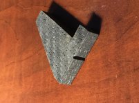
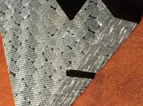
I have a question for you. I got my carbon fiber cut pieces from water jet cutter today. Because I ordered the carbon fiber from online source and sent it directly to the cutter, I have never seen the carbon fiber until today. Once I opened the package, I realized that the carbon fiber I ordered is not very solid. Please see the photos. It is strong structurally, but if I squeezed it really hard, I can squeeze some water out of the carbon fiber. I think the water was from the water jet cutting machine. I am not happy with it. I am not sure what I will do at this moment.
After searching online, I found some epoxy liquid for carbon fiber. If I sink the cut pieces into the epoxy, will the epoxy make the cut piece solid?
Attachments
Hi Jim,
I'm sorry to hear of your problem. The type of carbon fibre panel that you have purchased is normally made from prepreg sheets. Prepreg has the carbon fibre material preimpregnated with a special type of epoxy resin. This resin doesn't start to cure until it's temperature is raised. A panel as thick as the one you have purchased would be made of about 30 separate lamina or layers, each oriented in a different direction to give the panel similar stiffness in all directions. The correct method of laying up such a thick panel would be to lay up 4 or 5 layers then vacuum bag the panel. This squeezes any trapped air out, degasses, and forces the layers into intimate contact. The panel is then played up in this fashion, vacuum bagging every 4-5 layers until the desired thickness is achieved. The resultant panel is left in the final vacuum bag and placed in an oven. As the temperature rises the epoxy initially becomes runny which helps the epoxy from separate layers to flow into each other creating a strong bond. Ideally the oven is pressurized, an autoclave, that helps force the lamina even tighter together.
Your photos show a lot of voids. This suggests to me that the panel was layed up in one go without the degassing stages. It was vacuum bagged as evident from the surface texture. It definitely wasn't autoclaved. The high pressure of the water jet has forced its way into the voids and have probably delaminated the panel to some extent.
It may be possible to rectify this. First you need to get the water out. I suggest putting the pieces into a warm oven and letting it evaporate. Don't over heat, if the water boils it will expand and force the layers to delaminate further. You will need a low viscosity high temperature curing epoxy and a vacuum pump, some release film and a sealable container capable of taking a vacuum. Place the pieces into the container and pour in the epoxy until they are covered. Evacuate the container, any air in the voids will bubble out and be replaced with epoxy. Remove the pieces and wipe of any excess epoxy. Put a piece of release film on either side of the piece and clamp firmly between two flat surfaces, pieces of wood or metal plate for example. Place the clamped pieces into an oven and cure as directed by the epoxy datasheet. Cure and allow to cool. Remove the release film and trim any excess epoxy.
I hope that this is within your tool shops capabilities.
Niffy
Hi Niffy,
I looked online stores and found the epoxy for carbon fiber is thin liquid because the carbon fiber needs to be saturated to gain strength. So, I assume that if the carbon fiber I have now can absorb water, it must be able to absorb the thin epoxy, too. Once the epoxy cured, the carbon fiber will gain strength. I just don’t want too many small pockets inside of carbon fiber. It may damp too much. Once the thin epoxy cured, I will apply thick coat of epoxy on the surface the head shell.
I will try to make the head shell first and sand it to whatever the shape I want. Then, I am going to sink the head shell into thin slow curing epoxy to let the liquid soaked into the carbon fiber. Perhaps, I should leave it in the 80 degree oven for serval hours. Once it is cured. I will apply thick epoxy on the surface. Of course, I don’t have the vacuum equipment and am not able to do that.
Thanks for your inputs!
Jim
Hi Jim,
I believe that you have mentioned that you have several air pumps left over from previous air bearing supply builds. Could you possibly use one of these in reverse as a make shift vacuum pump? Any thing that reduces the pressure will help to draw out trapped air and allow the epoxy resin to fill the voids. A bicycle pump with the diaphragm turned over is another option. I would recommend doing each piece separately. If you glue the sections together you will block some of the passages that would allow trapped air out and fresh resin in. The water that got into the voids was under high pressure. I am doubtful that the more viscous epoxy at atmospheric pressure will penetrate anything like as well.
Good luck. If I can be of any assistance please just ask.
Niffy
Hi Niffy,
I talked to carbon fiber manufactory today and they told me that I should not use water jet to cut carbon fiber because it may delaminate the carbon fiber. It seems to me that I wasted some money. Anyway, I learn something now. They recommended CNC machine cutting.
Jim
I talked to carbon fiber manufactory today and they told me that I should not use water jet to cut carbon fiber because it may delaminate the carbon fiber. It seems to me that I wasted some money. Anyway, I learn something now. They recommended CNC machine cutting.
Jim
Hi Jim,
Water jet cutting is a standard method for cutting carbon fibre. I think your carbon fibre supplier is trying to shift the blame for the failure from his substandard product. If he had produced the carbon fibre well it would not have delaminated but it would probably have cost considerably more.
If you are planning on purchasing more carbon fibre for another attempt I would suggest using a thinner section in order to reduce the rather high vertical effective mass. I would personally use 1.5-2mm thick sheet. I would use these to make sandwich panels with a lightweight core. The best core material is end grain balsa wood. End grain has the grain of the wood at 90° to the plane of the panel, running up and down for a horizontal panel. This method of construction will reduce mass by 60-70% but still be 75% as rigid. This type of panel is also much better damped than a solid sheet. You will also find it's less expensive than thick solid sheets.
I am a die hard diy kind of guy and never outsource if I can help it. Carbon fibre is not difficult to work at home. Sharp drills, a fine tooth hack saw and sandpaper.
Niffy
This might sound like a stupid question....but it just came to mind....
Why making all these efforts trying different rails to lower friction, when in the reality the air media is very likely the most suitable for this application overall (provided you can drive your carriage system with very low air pressure to minimize turbulence on the parts thus vibration at the cartridge)?
To me it comes to mind Terminator tonearm. If that is the tonearm that inspires many linear tonearm makers, why going a different route?
I mean I know this sounds stupid, but if I have means and capabilities to do it, I would probably try to perfect that design, provided there is any further improvement to make!
I don't mean to say these developments are not worth it...they are very, very interesting, I guess I am just trying to gauge my idea with the more experienced folks here!
Hi,
why? Because we can and because we like to
Besides not everyone likes a bulky, noisy air pump in his listening room ... or another power line dependant device.
If You're interested in linear air arms, well, there are enough entries to digest and the possibility to open a own thread.
jauu
Calvin
why? Because we can and because we like to
Besides not everyone likes a bulky, noisy air pump in his listening room ... or another power line dependant device.
If You're interested in linear air arms, well, there are enough entries to digest and the possibility to open a own thread.
jauu
Calvin
Hi Niffy,
The carbon fiber I bought was economy one. In other words, it is not at its best grade. I bought this because it is the only one comes with 3//8” thickness. Again, I took a look these carbon fiber cut pieces last night. Actually, I don’t think it is delaminated. I think I will still use them and I also ordered thin epoxy liquid. I plan to sink all the pieces into epoxy first then to glue them together and sand them to the shape. Let’s see what will come out.
Thank you for your helps!
Jim
Stefanoo,
Your question is not stupid at all.
For a air bearing arm, the biggest obstacle is air compressor. Even for low air pressure compressor, its noise can be too much for quiet listening session. So, you need separate space to host the compressor. Another obstacle is the cost of air compressor. Low air pressure compressor is not too expensive. But I won’t recommend low air pressure air bearing arms personally.
I personally don’t recommend Terminator tonearm for two reasons.
1. Its bearing is not stiff enough.
2. Its construction is not rigid and compact enough.
Three are no variations for high air pressure air bearing arms. The higher pressure, the stiffer the bearing is. This is what we want for a high performance tonearm.
Hope this helps.
Jim
There are pros and cons to both systems. The main advantage to air bearing is virtually zero friction that is independent of carriage mass. My current line of experimentation will almost certainly result lower friction than the moving bearing type of air bearing, the flexible hose having greater resistance than my mechanical bearings. A problem with air bearings is that the air in the gap has a stiffness that acts exactly like a spring. This spring combined with the mass/effective mass of the arm has a resonant frequency that will be in the audio bandwidth. Damping will help to reduce its effect but cannot completely eradicate it without increasing to a level that inpinges on arm movement. An advantage of mechanical bearings is that low frequencies are damped by bearing friction and high frequencies, audio bandwidth, are controlled by physical grounding. However bearings friction is directly related to carriage mass via the coefficient of friction. With most bearings the coefficient of friction is to high. Bearing chatter is another problem if using ball race bearings. You either have to have a carriage that is to lightweight to offer adequate rigidity or a carriage that is so heavy that bearing friction is excessive.
My experiments are aiming at offering air bearing levels of friction without the air spring effect. This in turn allows for ideal carriage mass and the advantage of an ultra rigid carriage. My designs are also aiming at ideal grounding without the need for additional damping.
It may be that the ultimate system is air based but the cost is considerably higher and the need for an air pump is unattractive.
So far I have conclusively improved on ball race bearings and had a lot of fun doing so.
- Home
- Source & Line
- Analogue Source
- DIY linear tonearm