Might consider abandoning the breadboard for FR4 proto board with plated holes, 2-sided being best. Before you do, though, if you have a solid copper piece of FR4, or even copper tape, you could make a ground plane directly below your breadboard. For every signal current path there needs to be a decent equal current return path, with smallest loop size possible between the two. At these frequencies a typical ground arrangement usually works, but a continuous ground plane is best.
Another possible culprit could be the length of lead between the gates of Q1 and Q2 relative to their respective resistor junctions, R1/R3 and R2/R4. Current leakage and other stray effects could be feeding the sensitive gates.
I usually use the common versions of this, in various sizes. If you have eBay, it's also sold there.
Last edited:
Hi
Maybe just a tentative correction...
In post #834, an answer to the PCB dimensions question is "44.5mm x 82.5mm". I ran with that, put the PCB image into a tool to extract dimensions between the 2 mounting holes, found something weird, like 43mm = not per usual UMS spec which was weird to me.
I went back to the original article, that mentions the PCB dimensions: 1.7" by 3", with mounting holes spaced 1.575".
1.575inches is 40.005mm, much better to fit a Modushop panel (holes spaced 10mm*10mm) or UMS heatsink with holes spaced 20mm apart.
So, i guess this is just so that others might avoid re-using the 44.5*82.5 and be puzzled by the mounting hole spacing.
Regards
Look at post #686. FE '22 was revised and is NOT the same size as it was in the original article, parts were added and the board grew larger. The boards currently for sale in the store (V1) match the dimensions I gave. (If the store is truly only selling the latest V1 version as I believe they are, they need to update the picture as it still shows the old one...."V0R0")
Hi
Thank you very much for the info.
I knew there was a revision, but remembered the pot and so on, not the dimensions of the PCB!
Used your values, the images from post #686 and everything matches! Distance between the mounting holes 40mm...
Sorry about that and thank you for the correction/information!
HiIt's not done yet.....

How is the progress going?
Do you have any perspective on when this will be fully developed and available?
RGDS
I apologize if it is was answered: is it possible to use this FE to get balanced output?
Yes if you use two of them. That said I do have a design for one with balanced output.
It's not done yet.....
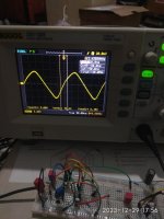
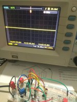
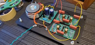
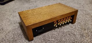
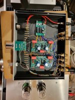
I have just finished building a new preamplifier with the DIY FE boards. I used a +/-15V Linear Regulated supply. It is very quiet, even with my bundle of snakes wiring  .
.
The sound is very good, I would describe it as sharp and detailed. I did not install any cap for C6, and the gain is set low. Thank you Mr. Pass for another great circuit!
.The sound is very good, I would describe it as sharp and detailed. I did not install any cap for C6, and the gain is set low. Thank you Mr. Pass for another great circuit!
Attachments
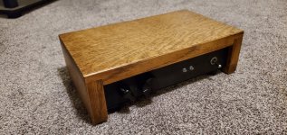

Well, I got this up and running just now after three or four self-inflicted wounds over the weekend. I didn't give it a long listen, just three or four tracks. It certainly "does what it says in the tin," as the Brits say. And what it says on the tin is lots of clean gain in a small, cheap package. I usually like to put a pre-amp in a full-size, or at least medium chassis, but I just couldn't justify all that empty space. I also used one of those microscopic Grayhill switches 6L6 featured earlier on this thread because I like a challenge; I don't think I'll do that again. All that's left to do is clean up some of the temporary fixes to the aforementioned self-inflicted wounds and listen more. I'm using a 48V Meanwell wall wart.
Thank you again, Mr. Pass. I've built F5, Aleph J, F6, M2x, B1 Korg, and two versions of H2V2. All have been fun and rewarding.
Since I'm not knowledgeable enough to assist others with troubleshooting or engineering, I guess one way to give back would be to list my hiccups so others may avoid them:
Thank you again, Mr. Pass. I've built F5, Aleph J, F6, M2x, B1 Korg, and two versions of H2V2. All have been fun and rewarding.
Since I'm not knowledgeable enough to assist others with troubleshooting or engineering, I guess one way to give back would be to list my hiccups so others may avoid them:
- Ordered and installed 47.5K resistors instead of 47R for R9 and R10. Luckily I had the proper value in stock.
- Installed R10 even though I was using single-ended power supply.
- Installed 681R for R6, then removed that to install P1. When it made no sound, removed the pots and re-installed 681R since I had no 750R on hand.
- Forgot to connect -In to V-.
Attachments
Hi.
Did one of the forum member got the opportunity to pair the Front End 2022 to the Ship of Theseus ? = is it working OK ?
Idea is to use the Ship of Theseus [being built] +36v single ended supply to also power the FE2022, creating an integrated amp (FE2022, 10k Alps Pot, Ship of Theseus in 1 box).
@6L6 mentionned FE2022 should be configured @Max Gain since Theseus was a follower. https://www.diyaudio.com/community/threads/diy-front-end-2022.394339/post-7283612.
Regards
- Home
- Amplifiers
- Pass Labs
- DIY Front End 2022