sorry to bothering you so much, this is still alchemy for me  ...
...
now when I know schematics of my OS and if I'd like to keep it what has to be done to make it optimum? should I change those R6/11 resistors to 300R as you suggested or just pair it with datasheet or? thanks...
...now when I know schematics of my OS and if I'd like to keep it what has to be done to make it optimum? should I change those R6/11 resistors to 300R as you suggested or just pair it with datasheet or? thanks...
Gustard DAC
Hi just got back into the Forum after a break and also wanting to tweak my system and have been looking at this... GUSTARD DAC-X12 DAC DSD ES9018 OPTIC/Coaxial/XMOS USB Asynchronous 384KHZ | eBay to add to my Musical Fidelity 3.2 CD Player and would appreciate any comments.
Alec
Hi just got back into the Forum after a break and also wanting to tweak my system and have been looking at this... GUSTARD DAC-X12 DAC DSD ES9018 OPTIC/Coaxial/XMOS USB Asynchronous 384KHZ | eBay to add to my Musical Fidelity 3.2 CD Player and would appreciate any comments.
Alec
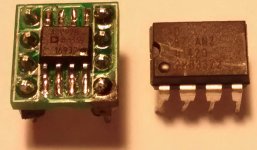
I purchased 6x AD797B in RS.
I put in the weilliang DAC. Measures are identical to 6x AD797ANZ received from Weilliang Chinese manufacturer.
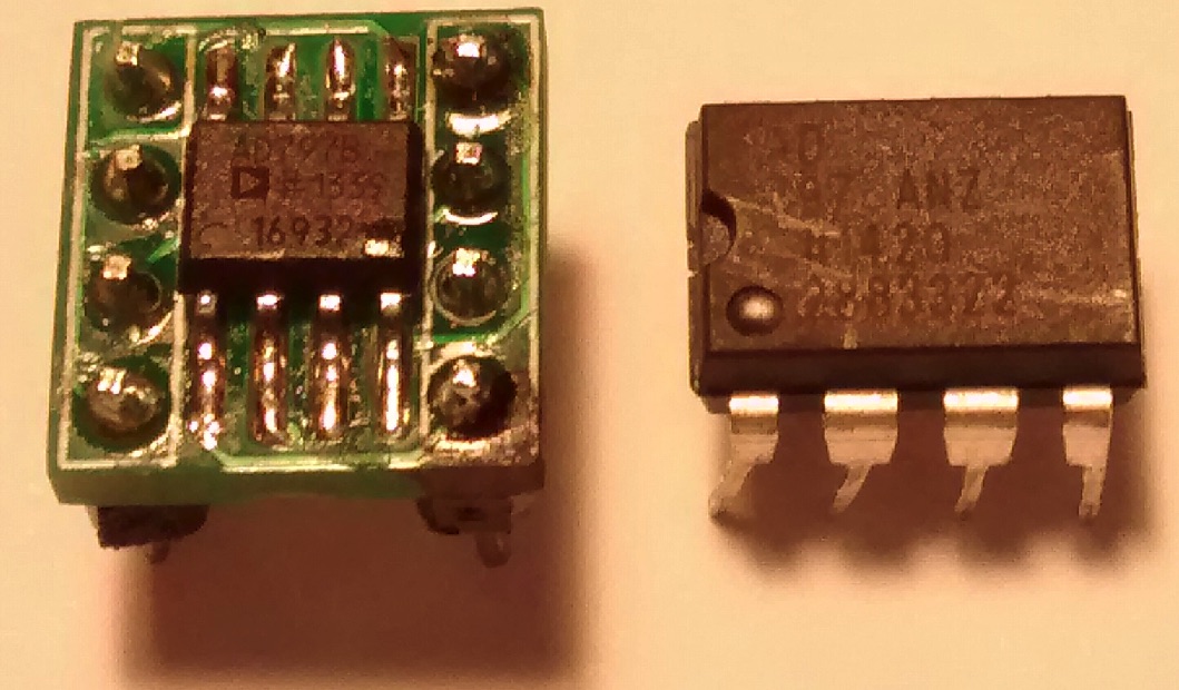
I think the AD797ANZ received from Weilliang are originals.
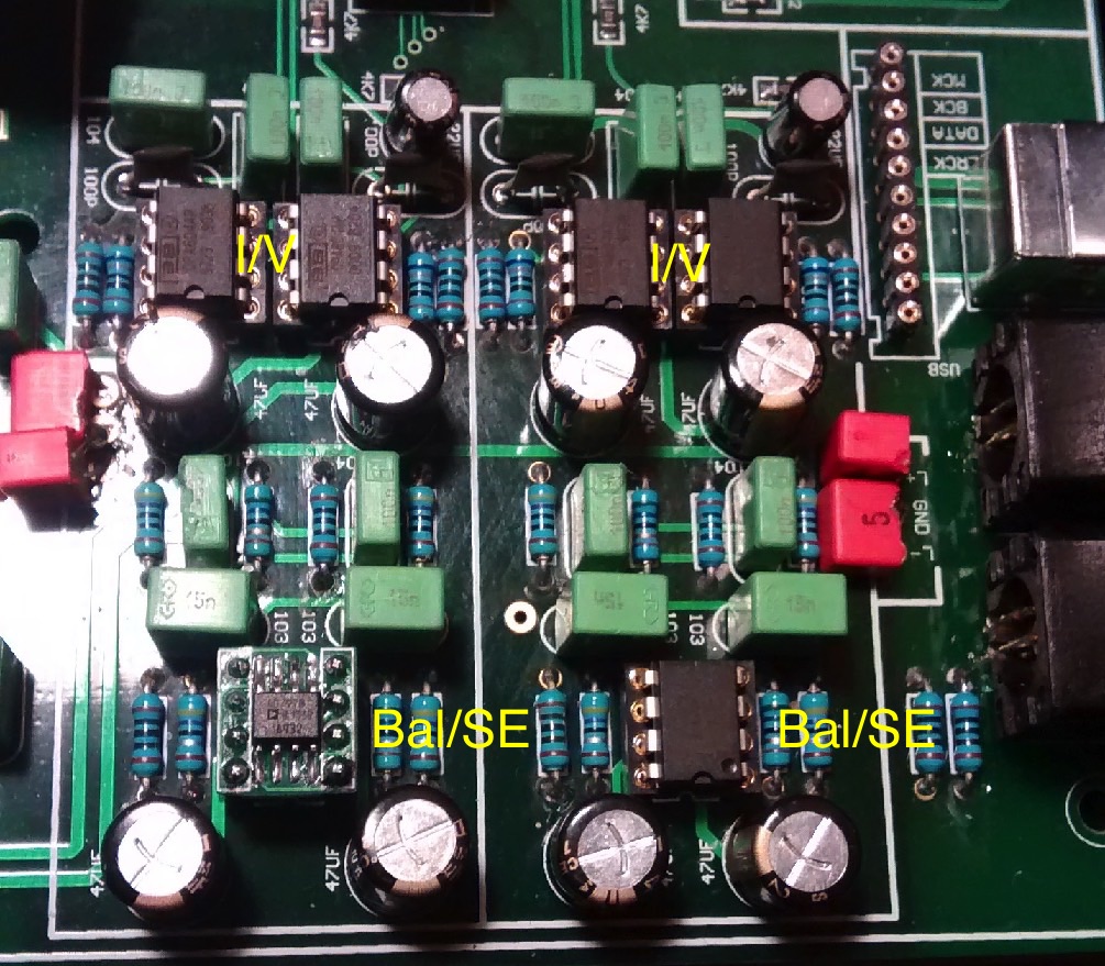
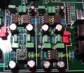
And oscillate in the circuit I / V like AD797B. Also original RS AD797B oscillate. But they work very well in the output Bal / SE.
I have found that the 4x I / V is very hot AD797B like AD797ANZ. And 2x output buffer balanced to SE no hot AD797B like AD797ANZ.
4x I/V OPA604 is not hot.
2x Bal/SE AD797 with 4x I/V OPA604 is better measures than 2x OPA604 or 2x LME49710 .
Attachments
Hi just got back into the Forum after a break and also wanting to tweak my system and have been looking at this... GUSTARD DAC-X12 DAC DSD ES9018 OPTIC/Coaxial/XMOS USB Asynchronous 384KHZ | eBay to add to my Musical Fidelity 3.2 CD Player and would appreciate any comments.
Alec
There's nothing much DIY about it, its a 9018 DAC in a ready built package.
What sort of comments were you hoping for?
I too got a Weiliang's ES9018 dac, 4 layers pcb with 0.1ppm oscillator upgrade. In stock form it sounded quite good.
I had since upgraded some of the parts that improved the clarity :-
- changed the stock 5534 opamps to bob opa134.
- changed the digital PSU caps fm ero to Panasonic fc 6800uf and os-con 680uf
- changed the analog PSU caps to nichicon muse kz
- changed the bypass cap to wima mks2.
I'm waiting for the lme49990 to replace the 134.
Have anyone tried tubes instead of opamps?
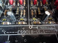
I've finally gotten round to giving my 2 layer board an overhaul. A close inspection appears to show 4 resistors fitted where there should be capacitors.
LC2 & LC10 are marked on the schematic as capacitors with a value of 100P (101 caps maybe?) They are adjacent to the dual opamp. Same for the other channel.
It seems the board has been fitted with 0.1ohm resistors instead.
LC2 & LC10 are marked on the schematic as capacitors with a value of 100P (101 caps maybe?) They are adjacent to the dual opamp. Same for the other channel.
It seems the board has been fitted with 0.1ohm resistors instead.
Attachments
Last edited:
Yes those are caps with a color band indicating their value. In the past also caps were color coded and some Japanese manufacturers still make caps in this form. To distinguish them from resistors they tend to give them odd colors like light green. Just leave them or, if you want the best of the best, change them for styroflex caps. They are definitely NOT 0.1 Ohm resistors.
http://www.csgnetwork.com/capcccalc.html
BTW why are the 10 µF decoupling caps (electrolytic) gone ?
BTW 2: if those 22 µF caps are the output caps changing them for MKT 22 µF will really give a benefit.
http://www.csgnetwork.com/capcccalc.html
BTW why are the 10 µF decoupling caps (electrolytic) gone ?
BTW 2: if those 22 µF caps are the output caps changing them for MKT 22 µF will really give a benefit.
Last edited:
Well I already replaced some cheap blue caps with the red WIMAs you see in the picture and removed the 10uF decoupling caps as I am part-way through upgrading the board. The 6 smoothing caps in the digital supply have also gone.
There is a significant problem with noise in this DAC which is why I am looking to upgrade it's components. I did not rule out any type of idiocy with the build, as the 22uF caps are actually again 10uF.
It does seem to be a capacitor in the photo but the colour bands do not calculate to 100Pf.
There is a significant problem with noise in this DAC which is why I am looking to upgrade it's components. I did not rule out any type of idiocy with the build, as the 22uF caps are actually again 10uF.
It does seem to be a capacitor in the photo but the colour bands do not calculate to 100Pf.
Measure them in that case, I think they're 100 pF. I would use styroflex there but I stock those. They are possibly hard to find nowadays. You can't go wrong with Panasonic FC 10 µF 50V for decoupling the IC but beware that you buy the "thick" version and not the ultra thin version (yes there are 2 versions 10 µF 50V). Replace the 10 µf output caps for 22 µF 16V MKT. If you can't find them I can supply those as I bought the very last batch from Wima a couple of years ago. Don't think of DC coupling unless offset is 0 mV Beware I don't know this DAC so I assume the 22 µF are output caps. Please find out if they are.
What you see is a manufacturer skimping on parts where it is possible. As always electrolytic caps is where they can gain most.
Beware I don't know this DAC so I assume the 22 µF are output caps. Please find out if they are.What you see is a manufacturer skimping on parts where it is possible. As always electrolytic caps is where they can gain most.
Last edited:
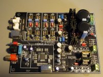
Here is the full board.
I have already made some changes:
The two large caps top right and all of the red ones are now Panasonic.
The larger electrolytics to the left of the heatsinks were Silmic II on delivery
The small red electrolytics are now Wima MKS2
I have got Panasonics to fit where caps have already been removed.
Can someone help me scope out what else to replace?
Attachments
Beware I don't know this DAC...
In that case please let those others who do know this DAC answer my questions.
Hay
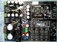
That board is not brilliant design. I have it year or more back. I start to build it but i noticed quite some mistakes.I don*t know anymore because that dac was not interested anymore because of just spdif input... also usb input is spdif input.
If i remember corectly...something was vrong around RCA gnd..i think it is connected wrong.
15V regulators are quite noisy, i redesigned it and it was ok but not perfect. Use L or 4.7-10R resistor and cut the lines to opamp suply lines.
Decouple 1uf before and after all 3 ADP151.
I think that also one resistor on spdif input is not ok ...i think it is 10k around LMV spdif ic...
cut out those reistor capacitors...put 68-100p wima or mica, styroflex are hard to find.
22Uf cap change to 10uf tantal and 1uf mkt...this is important filtering of offset pin voltage. it brings a lot in mycrodynamic. Ic decoupling caps 47uf KZ or FC. and under the board some 100-470nF mkp or pps or mkt or ceramics.
That was my version before i stop to do it further.
Attachments
In that case please let those others who do know this DAC answer my questions.
I know a lot of DACs and output caps are output caps, same counts for decoupling caps. Your attitude does not help either. In fact I think it is thick and rude which is not the best of combinations.
Last edited:
Don't take it personally. I have Asperger Syndrome and my responses are often mistaken for rudeness. I certainly have no intention of making any moderators angry!
I made a post in this thread because I have the DAC in question and have posted here in the past. I did not want you to be offended by appearing to be ignoring your advice, so I clarified that I was waiting for a response from those who were familiar with the board. Unfortunately you were offended anyway.
The reason for posting here was to get a response from maybe Spirovious and those others who own the DAC, but I appreciate you taking the time to try and help with my question, particularly in teaching me that there are capacitors around which look just like resistors.
And yes, I am thick. I've had this board for 2 years and still have not solved the noise problem. It may not be brilliantly designed but I'm sure it can be made quieter so I am still working at it.
Last edited:
What dropout???
Hi,
The ESS 9018S Dac which I just finished designing and posted on this site has been playing music for 72 hours straight with no dropouts at all. It is solid as a rock!!. It is designed to the letter of the ESS spec. It has a 100MHZ Mems oscillator, the highest quality precision LDO's from TI and Linear Technology. It is a four layer board with a separate analog ground plane, separate chassis ground and full digital ground plane. Also, the outer layers are completely flooded with ground. Any board that has less the 17 caps closely surrounding the 9018 DAC chip does not meet the ESS requirements. My board uses an extremely good Burr-Brown TI opamp. I could go on and on and on. The only place my board can be found on the internet or anywhere else on the planet is on this site. This DAC sounds better than my Chi-com Dual Wolfson DAC, Better than my Meridian DAC, Better than my Arcam DAC, blows away anything by Sonos. I am currently listening to it via a Krell KS7P, Krell KSA250 and B&W802's and it sounds sound incredible!
If I sound upset, well I guess I am. My post has received not a single reply. There is no interest at all. To think, I was willing to listen to your ideas and consider creating A custom board tailored to your needs for the fun of it.
Gmaff
- Home
- Source & Line
- Digital Line Level
- DIY ES9018 Hi-end USB DAC