Yes, it would be quite feasible to use a copper mesh if you don't mind the extra cost.
When I had set out to build my panels I wanted to use steel window screen so that I could solder the connections to the screen.
But it is not an off of the shelf item like it was years ago so I ended up with aluminium screen.
I haven't had any major problems connecting to aluminium as I have tried several methods, but, soldering is not one of them.
Copper would be very pretty after it is clear coated.
I have some stators that I made out of 1/16" copper clad TIG rod that I will either replate in copper to cover up the solder or maybe gold electroplating before they get a coating of clear acrylic. jer
Here is a list of threads I composed a while back.
There are a quite a few more that need to be added but it is a good place to start with a wealth of information. jer
http://www.diyaudio.com/forums/planars-exotics/167871-help-advice-information-reassurance.html
There are a quite a few more that need to be added but it is a good place to start with a wealth of information. jer
http://www.diyaudio.com/forums/planars-exotics/167871-help-advice-information-reassurance.html
Sounds very interesting. The only thing I'm stuck on is the coating for the diaphragm. Some of the materials aren't available here in Canada (import/export legal BS). I've been monkeying with a combination of black ink and a very small amount of powdered Graphite, but alas the resistance is rather low. Not sure if it's the ink or the graphite or both.
Does look nice. Kinda like a dark gunmetal grey. Should save it as a paint colour.
Does look nice. Kinda like a dark gunmetal grey. Should save it as a paint colour.
I have done some experiments using the PVA glue trick however I have not tried it as a diagphram coating on a working panel yet.
I might just give it a try out of curiousity.
On my rebuild I did use PVA glue very heavly doped with graphite for the charge ring and as a conductive glue.
This worked great!
But I still had some nickel print and I had used that to mend the broken stator connections.
I am thinking about trying it for stator connection on the next build in order to get away from using exotic hard to get materials.
However, Try to get a can of LICRON CRYSTAL if you can.
This stuff simply cannot be beat at the moment.
jer
I used a ratio 1:8 to 1:10 glue/water and it took A few drops of dawn dishsoap to get it to properly wet the mylar without pooling up into one huge droplet as it dried up.
Leaving a fairly transparent coating that seemed to adhere well to the mylar and its thickness was unmeasurable with my micrometer.
There are some closeup pics of it somwhere in those threads.
I still have that same sample, And after a year of being tossed around and handled the coating still does not readily come off when I rub it in between my thumb and fingers.
Infact upon re-examining it,it has no sign of deteriation.
There is also a heavy discussion of wheather or not the ink makes any difference and whether or not the graphite make too little resistance.
I believe a few have claimed that neither are needed.
There is also a question of how well it works in varying degrees of humidity.
Some say not so well in the dryer area's of the globe.
Charlie has used dish soap on one of his panels before, and, he said it worked.
So I'm thinking that the little bit needed in the water/glue for wetting might be suffciant.
So I might just try it so that I can save my precious licron for my larger final build.
jer
Last edited:
Hi,
though I am certainly an advocat of sheet metal stators, I started with building wire stators many years ago.
When I was just a little boy, I asked my mother, what will it be.... Will it be wire? Will it be sheet? Here´s what she said to me: "Que sera sera....Whatever will be will be........".
Both methods have their pros and cons and the choice depends on what kind of panel You intend to build, Your budget, Your manual skills and the amount of work You´re prepared to invest.
Wire is good for flat panels while the best sheet metal stators are curved. If You want to stay flat, stay with wire.
If You intend to achieve a lower bandwidth limit below say 150Hz, stay with wire. Anywhere above 150Hz and curved metals are an alternative.
Wire is easily sourcable, cheap and relieves You from finding well coated metal sheets or to coat them Yourself.
It takes quite a bit of work to get all the wires perfectly straight if You don´t build a wire stretching jig. Sheet metal is lower on Your personal work effort if You can get prefinished, coated and curved sheets. It´s alot of work though if You try to coat them Yourself. Be prepared to not be able to find a coater who is really able to do the job. They all promise: "Yes, we can..no problem." My experiences talk different. Over the last 25 years not one(!) coater delivered a coating that met the demands with his first try.
Wire allows for easy electrical segmentation and amplitude equalization, which reduces capacitive loading at the upper end of the frequency range and lowers the need for external equalization. This makes such panels typically an easier load to drive. Sheet metal panels feature a large and constant capacitive load which allows for lower transformation factors and better sounding audio transformers.
Chance of success is greater with wire stators. Curved metal sheets require a detail knowhow from builder and suppliers that usually takes several attempts before success.
There are small sonic differences between both styles and I prefer the increased dynamics of curved sheets panels, but both methods allow for a sonic quality way beyond dynamic drivers.
jauu
Calvin
"Wrinkels wrinkles go away, back to the face of Doris Day" (prayer of an ESL-builder while stretching diaphragms)
In my experience, perf-metal stators and 3M urethane foam tape is the easiest method to make ESL panels, but not the highest performance. The non-segmented nature of these designs means that you'll have laser beams of sound at higher frequencies. Combine these with a good transmission line enclosed woofer and you will be able to de-bone chickens in the sweet spot when it comes to dynamics. But if you move a foot or so away from the sweet spot, you'll lose huge amounts of treble energy. Here's a horizontal polar plot of my 48" x 18" ESL panels:
http://quadesl.com/speaker/diyesl/polar_2.gif
Here is just the first 5 degrees of rotation:
http://quadesl.com/speaker/diyesl/polar_fine.gif
Dispersion is largely non-existent, and the speakers are a one man ride. the power response is not flat either due to the dispersion being so different throughout the spectrum.
Wire stators are the best choice (IMHO) for a really balanced non-beamy ESL, but they are a lot harder to construct, and EQ than a single big-ol' element.
Sheldon
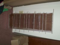
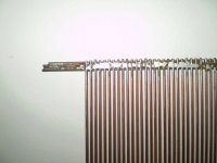
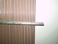
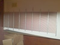
Here is another method that I used to make wire stators.
Although I have not finished them yet.
I did go through A couple of soldering guns to complete them as I did this on my desk during one winter.
The plan was to build a jig so that I could use a small torch to quickly and evenly solder the the supports.
But I never got that far, aswell as finishing them(he,he,he).
But, Hopefully I will get to them this summer as I still need two more in order to build two six foot panels.
I am thinking about cutting on fo them into segments and just build a 3' two-way panel.
They are made from standard 3' X 1/16" tig wire spaced 1/16" apart.
And they just need to be coated with some clear acyrlic or polyurethane for a stator insulation coating.
I had experiemented with different support spacing and I had found that one or none will be needed once mounted in a proper frame structure.
But two is plenty as they have been shoved around for seven years without being damaged as thet are qiute heavy.
It was quite a job and very time consuming to build them by hand that is why I would suggest the extra effort of building a jig if you plan on building more than 4 of them.
Enjoy DIYer's ! jer
Attachments
-
 STACK OF SIX STATORS.jpg91 KB · Views: 1,143
 -
 SPACING COMB JIG.jpg116.2 KB · Views: 1,101
 -
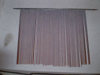
 ONE TIG STATOR.jpg79.7 KB · Views: 1,080
 -
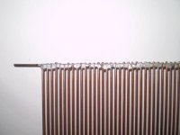 CLOSE UP OF ONE END.jpg88 KB · Views: 1,067
 -
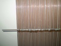 CLOSE UP OF MIDDLE SUPPORT.jpg124.7 KB · Views: 1,070
 -
 CLOSE UP OF ANOTHER SUPPORT END.jpg89.1 KB · Views: 280
 -
 CLOSE UP OF ANOTHER MIDDLE SUPPORT FRONT.jpg116.3 KB · Views: 247
 -
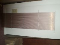
 ANOTHER ONE WITH DIFFERENT SUPPORT SPACING.jpg97.9 KB · Views: 325
It is amazing as to what you can do with enough determination.
I made those in the winter of 05-06 and then got stupid with a DUI and that set all of my projects back awhile.
I'm not afraid to admit my to mistakes hoping that it will stop some one else from doing the same, As I had learned the hard way !!! jer
I made those in the winter of 05-06 and then got stupid with a DUI and that set all of my projects back awhile.
I'm not afraid to admit my to mistakes hoping that it will stop some one else from doing the same, As I had learned the hard way !!! jer
Hey, speaking of copper mesh, check this stuff out:
Copper Blocker - Lee Valley Tools
This would be plenty fine and open enough for the stators?
Copper Blocker - Lee Valley Tools
This would be plenty fine and open enough for the stators?
I can't get I good closeup on it.
I might be copper clad.
I wonder what size the holes would be once it is stretched taut?
It is only 5" wide but you never know.
I wanted to try using some rabbit screen material,the galvinized stuff with 1/4" square holes.
I once had source for some that had 1/8" square holes and would be perfect but I can't seem to find it anywhere now. jer
Try it! You will never know unless you do.
I can't say for sure because I don't have A good close up of the material.
But chance are you might have a hard time getting it to be perfectly flat as close tolerances are required.
Typicaly < 5 mil and no more than 10mil over the entire span of flatness to keep the diagphram stable and 15mil is realy pushing it but may be acceptable.
But you never know, so check it out and let us know what you find. jer
- Status
- This old topic is closed. If you want to reopen this topic, contact a moderator using the "Report Post" button.
- Home
- Loudspeakers
- Planars & Exotics
- DIY electrostatic speakers for dummies