Then there is layout , the power supply .. how big the output stage is (damping factor)...
The simulator can tell you the circuit works , that it will not oscillate (provided you did lay it out right), what the idle currents are, and roughly how linear and distortion free it MIGHT be.
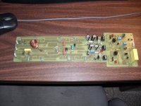
Until you convert that sim into the real world (below) , you are just "playin' around" with what you trust to be the most accurate models of the real thing.
What matters more can be the reviews of a certain topology. I read 100's of luxman M120a reviews before I even contemplated taking a chance to actually build one. I am so paranoid I even made a pair of the AX's as backup. I KNOW they sound and work good...(first amp I built- the blameless).
OS
The simulator can tell you the circuit works , that it will not oscillate (provided you did lay it out right), what the idle currents are, and roughly how linear and distortion free it MIGHT be.
Until you convert that sim into the real world (below) , you are just "playin' around" with what you trust to be the most accurate models of the real thing.
What matters more can be the reviews of a certain topology. I read 100's of luxman M120a reviews before I even contemplated taking a chance to actually build one. I am so paranoid I even made a pair of the AX's as backup. I KNOW they sound and work good...(first amp I built- the blameless).
OS
Attachments
According to this, after the amplifier is built and some layout is used, a PSU is designed and used, more measurements and listening are required. This is becoming more and more interesting indeed, the whole system counts starting form early simulation stages to final system in the new housing. But layouts introduce another major factor here, that simulations don't show, so how right is right ostripper when it comes to PCB layout? How do you tell that you laid it out correctly, I am interested to know what things do you look at in your layout and what rules you recommend us to follow.
Last edited:
There was a Thread by a UK Member building (I think) a blameless. He found unexplained distortion from his 1st PCB layout. Better with his second Layout. He chased many ghosts, but it turned out to be a voltage distortion effect on a resistor that would not tolerate near, but still less than, voltage rating when being power tested........... so how right is right... when it comes to PCB layout? How do you tell that you laid it out correctly, I am interested to know what things do you look at in your layout and what rules you recommend us to follow.
Can someone remember his name?
Then there is layout , the power supply .. how big the output stage is (damping factor)...
The simulator can tell you the circuit works , that it will not oscillate (provided you did lay it out right), what the idle currents are, and roughly how linear and distortion free it MIGHT be.
Agree..
Construction must be meticulous...
Btw, the resistor inside the output coil
is not a good idea, as it s source of distorsion
at high currents...
Conclusion: There are three criteria by which modern amp designs are judged.
#1 Measured THD et al
#2 Simulated THD et al
#3 Subjective listening.
Since #3 is unreliable, it is downplayed.
But #1 and #2 don't always correlate well with the listening experience.
What to do?
Agree and many who listen know there is no relationship or very little between low THD and sounding good, THD is just one of many criteria necessary for a good amplifier and how much is good enuff really , every action brings a reaction .
There was once a time when many felt TIM was the most important. Power amplifiers are all about the PSU, you first have to start there IMO...
Wahab has provided us with his SIM's any conclusions or opinions from
such?
THD was one of the parameters simmed..
As for sounding good, one must explicit what he means
by "sounding good"..
For me, this means sound accurate as i can make
you listen a 3% distorsion amp with "choosen THD"
that will at first look sound better than a 0.1% one
if one is not aware of the original sound.
Since we were neither at the sound recording sessions,
nor at the mixing ones, we don t exactly know what was
the original sound, so the only thing left is to have
an amp that is the most accurate possible.
Of course hi end hifi imply that no tone correction
is used , yet, some so called audiophile compensate by
using amps providing high level of mainly even order THD
in replacement of the said tone controls and then claim
that the sound is slightly brighter, with "more space"....
I hear you Wahab,
Have to say your 3% THD is a bit extreme , I'm more concerned with the .003 vs .00012 THD, when THD is only one parameter in judging an amplifier and i cannot speak for anyone else , but I'm very confident i can tell you a poor sounding amplifier when i hear one.
I'm also very keenly aware of designers and engineers who shy away from subjective evaluations , as they do none themselves. It is not coincidence that successful designs are from those designers who either listen or take subjective evaluations into account themselves.
Your sims results are very informative, especially if we are able to recognize sim results with a specific type of sound ( good or bad) and I'm assuming the results are based on the PSU being absolute.
Again i would like to ask , based on your Sim results , what have you been able to determine from the various designs and why ?
Anyone ?
Regards,
More coments like this in post #279 http://www.diyaudio.com/forums/solid-state/164093-100w-ultimate-fidelity-amplifier-28.html can help.
Again i would like to ask , based on your Sim results , what have you been able to determine from the various designs and why ?
Anyone ?
The easier to determine is the designer s guidelines..
Almost all designs are directed toward low THD.
Stabilty is not the main design goal, as all the AB class amps
are stable thanks to the output LR filter.
JLH10W and Pass F5 are a different matter, since
THD content is the cornerstone.
As showed by the relevant graphs, clipping behaviour
wasn t checked seriously , apart from Pass F5 and
leach amp , but this latter, due to its implementation
has intrinsical good cliping response without having
to implement a clamping.
Apex did correct an early version rail sticking,
but at the expense of some marginal increase
of THD, although the final clipping figure is quite good..
Last edited:
Hi a.wayne,
Well, don't forget that the entire purpose of this thread was to introduce the work of simulating some amplifiers that wahab did. He included popular DIY amplifier designs because many members had built at least one and have a personal familiarity with them. Examining these various amplifiers from a simulation point of view is perfectly valid for this exercise.
The larger question concerning the suitability of a simulation substituting for the real thing, and how well it does or does not correlate really is the topic for another thread. After all, the models matter and there may be other variables that one could select for running the simulation that might affect the quality of the end result. I don't believe for one second that the goal is to design the circuit completely via simulation and run it into production. However, a simulation is probably the best way to examine overall trends when you try different ideas out. In other words, a good simulation can tell you whether or not a circuit idea might be feasible or not. Note that in this case, the word "good" is referring to a properly set up simulation run, not whether or not you like the outcome.
Any comments that wahab may make are his opinion as well. The criteria he used to make those judgment calls are laid out before the world for all to see (as opposed to "in my system" type comments). So whether or not anyone feels that simulated results don't agree with their ideas is completely irrelevant in this thread. Wahab is talking about comparisons made between circuits in simulation, and how he would decide what things he would look for in a good design. That information is both valid and something that can be discussed based on the fact that the data is here for all to see.
Hi metal,
One thing is certain though. If "ideal reproduction" were possible, then how many of us would use tone controls to modify the performance to be more to our liking? I think the question comes down to defining the word "reproduction" in order to remove personal bias. If we accept "reproduction" to mean that the produced sounds are as close as possible to the original sounds, talking about it can progress. If a person prefers a coloration to music (for example), then what sounds the best to them will never be true to the original. A no-win situation because you then are involved in an argument about whose tastes are correct. No thanks!
So to stick to the definition of being completely faithful to the original sounds, then the system that performs with the least amount of distortion and other aberrations (to cover those who interpret that as THD only) is by definition, the most accurate system. In other words, it most closely reproduces the original sounds.
Use an effects unit to colour the overall sound to whatever tickles your fancy. A system that colours everything a certain way is, by definition, not a low distortion system. By extension it would also be defined as something other than "high fidelity" or accurate. Stereos are not guitar amplifiers and are not tasked with creating music. The entire purpose of a stereo system is to reproduce sound as accurately as possible for that price point. Other factors such as appearance, features and imperfections in sound reproduction are the reality of today's systems. People tend to break in to groups that really show what defects they can accept and which they can't, given that they can all afford what they want. If money is a constraining factor, acceptance of defects becomes a stronger factor in deciding what to listen to.
I do have to ask a question at this point though, since your preferences are listed as a signature line under each post you make. Have you built and listened to any other amplifiers in the listed simulations? If so, how many of them? Do you also recognize that the sound quality of each design varies according to the quality of PCB layout and the parts used. Therefore, many amplifiers of the same design may sound totally different. (..!) That's another critical point that bears consideration.
Let's not discuss these side issues, they belong elsewhere. If you don't like simulations, then this thread is not one you should be reading.
-Chris
Well, don't forget that the entire purpose of this thread was to introduce the work of simulating some amplifiers that wahab did. He included popular DIY amplifier designs because many members had built at least one and have a personal familiarity with them. Examining these various amplifiers from a simulation point of view is perfectly valid for this exercise.
The larger question concerning the suitability of a simulation substituting for the real thing, and how well it does or does not correlate really is the topic for another thread. After all, the models matter and there may be other variables that one could select for running the simulation that might affect the quality of the end result. I don't believe for one second that the goal is to design the circuit completely via simulation and run it into production. However, a simulation is probably the best way to examine overall trends when you try different ideas out. In other words, a good simulation can tell you whether or not a circuit idea might be feasible or not. Note that in this case, the word "good" is referring to a properly set up simulation run, not whether or not you like the outcome.
Any comments that wahab may make are his opinion as well. The criteria he used to make those judgment calls are laid out before the world for all to see (as opposed to "in my system" type comments). So whether or not anyone feels that simulated results don't agree with their ideas is completely irrelevant in this thread. Wahab is talking about comparisons made between circuits in simulation, and how he would decide what things he would look for in a good design. That information is both valid and something that can be discussed based on the fact that the data is here for all to see.
Hi metal,
Well, that's a long limb to be out on. First, how can anyone be positive that the simulated performance agrees with the physical amplifier? Then you have speaker - amplifier interactions on top of that. In short, you are attempting to equate simulated performance with real world performance.May be the very low distortion amplifier Wahab likes, sounds dead to others
One thing is certain though. If "ideal reproduction" were possible, then how many of us would use tone controls to modify the performance to be more to our liking? I think the question comes down to defining the word "reproduction" in order to remove personal bias. If we accept "reproduction" to mean that the produced sounds are as close as possible to the original sounds, talking about it can progress. If a person prefers a coloration to music (for example), then what sounds the best to them will never be true to the original. A no-win situation because you then are involved in an argument about whose tastes are correct. No thanks!
So to stick to the definition of being completely faithful to the original sounds, then the system that performs with the least amount of distortion and other aberrations (to cover those who interpret that as THD only) is by definition, the most accurate system. In other words, it most closely reproduces the original sounds.
I can.I can't believe that the laws of physics say that the best sounding amplifiers have extremely low distortion whether simulations or measurements, do they really sound good for all music colors and for all people?
Use an effects unit to colour the overall sound to whatever tickles your fancy. A system that colours everything a certain way is, by definition, not a low distortion system. By extension it would also be defined as something other than "high fidelity" or accurate. Stereos are not guitar amplifiers and are not tasked with creating music. The entire purpose of a stereo system is to reproduce sound as accurately as possible for that price point. Other factors such as appearance, features and imperfections in sound reproduction are the reality of today's systems. People tend to break in to groups that really show what defects they can accept and which they can't, given that they can all afford what they want. If money is a constraining factor, acceptance of defects becomes a stronger factor in deciding what to listen to.
I do have to ask a question at this point though, since your preferences are listed as a signature line under each post you make. Have you built and listened to any other amplifiers in the listed simulations? If so, how many of them? Do you also recognize that the sound quality of each design varies according to the quality of PCB layout and the parts used. Therefore, many amplifiers of the same design may sound totally different. (..!) That's another critical point that bears consideration.
Let's not discuss these side issues, they belong elsewhere. If you don't like simulations, then this thread is not one you should be reading.
-Chris
Last edited:
About Luxman amplifiers, can someone try one of the three variants Diy luxman exposed here (you must log in if want download them):
LuxMan DIY Audio Amplifier (colectia Tehnium Azi) - Comunitatea Tehnium Azi - Pagina 3
Sound is not only a specific set of amplifier topology, but rather is determined or influenced by the active components used in manufacturing quality audio amplifier or precision grading transistors. And that's not all!
Regards.
Hi donpetru,
Interesting idea.
I've serviced the real things for years, and I think they sound pretty good. Certainly, they don't have many bad habits.
Since I have the matching C-120A here, building one (M-120)seems like a good project. I also have an L-450 here to compare with.
Huh, sadly I can't read the language there. I'll have to go from the service manual instead. That'll take some time as the PCB has to be designed first.
-Chris
Edit: I see they started off with an M-02 first. Now, that's a good choice. I've recommended that system often to people assembling a sound system using older components. I might actually go that way instead.
Last edited:
Examining these various amplifiers from a simulation point of view is perfectly valid for this exercise.
The larger question concerning the suitability of a simulation substituting for the real thing, and how well it does or does not correlate really is the topic for another thread.
However, a simulation is probably the best way to examine overall trends when you try different ideas out. In other words, a good simulation can tell you whether or not a circuit idea might be feasible or not. Note that in this case, the word "good" is referring to a properly set up simulation run, not whether or not you like the outcome.
-Chris
Hi , Anatech
Very good points, indeed.
As an exemple of your points, here a graph that display
the clipping amp output and the corresponding current
of the VAS buffer of a blameless amp , that is by the way
simmed in this review,if ever the said transistor has not its
current limited by a resistor or whatever current limiting circuit.
As shown by the graph, instantaneous current jump to a whopping
450mA , and with a PS of +-35V, the said bjt who see about 34V VCE
will have an instantaneous power dissipation of about 15W, somewhat
high for a BC556.
Just remember that the output is normaly loaded, with 8R.
This extra current is just due to clipping , not a low load..
Simulation allow non destructive tests that would be financially
and timely wasteful in real world implementations...
cheers,
Attachments
Agree..
Construction must be meticulous...
Btw, the resistor inside the output coil
is not a good idea, as it s source of distorsion
at high currents...
professor leach wraps the inductor right around the 10r resistor on the leach amp , ALL the quasi MOSFET amps are the same , The national semi reference boards for both mosfet and BJT have the resistor inside as well . very few I see any different unless the design omits the resistor all together. If you have documentation on this effect ,please contribute.
OS
Eddy current - Wikipedia, the free encyclopedia
Hi donpetru,
Interesting idea.
I've serviced the real things for years, and I think they sound pretty good. Certainly, they don't have many bad habits.
Since I have the matching C-120A here, building one (M-120)seems like a good project. I also have an L-450 here to compare with.
Huh, sadly I can't read the language there. I'll have to go from the service manual instead. That'll take some time as the PCB has to be designed first.
-Chris
Edit: I see they started off with an M-02 first. Now, that's a good choice. I've recommended that system often to people assembling a sound system using older components. I might actually go that way instead.
The m120 used c2240/a970.. "dead ringers" for my F grade c1845/a992's , my only change is the better OPS I use , a triple back then can be matched by a standard EF2 now , my PB250 has a current gain of at least 5k without the Tcomp and stability issues of luxmans triple. also , it seems luxmans use of the hawksford predated hawksford's writings
 he(hawksford) brought it to a new level and in simulation I beat the original by a factor of 5 (.015 to .003%) , and that is at 200+ watts / THD20.
OS
I do have to ask a question at this point though, since your preferences are listed as a signature line under each post you make.
-Chris
I am using the signature to make it easier for people who participated in Dx group buy to access currently offered Dx PCBs and BoM, also to show my version that I have built recently. My signature barely reflects all my amplifier preferences, Dx Blame is one of them, but my preferences are not only limited to Dx Blame ES, I am using the signature for the sake of group buy participants quick links.
Last edited:
Hi wahab,
Excellent thread, a very worthwhile contribution.
If I remember my high school physics, eddy currents only occur when a conductor cuts the lines of magnetic force i.e. its moving, but that was a long time ago.
I have played around (rather than a scientific experiment) with inductors and sticking a resistor up the centre. In a static envirnoment a carbon resistor didn't effect the actual inductance by much (if any).
I have made a little external PCB to test this further in the future.
regards
Attachments
Last edited:
Hi wahab,
Excellent thread, a very worthwhile contribution.
If I remember my high school physics, eddy currents only occur when a conductor cuts the lines of magnetic force i.e. its moving, but that was a long time ago.
Hi, Greg
That s one case,i.e, if the conductor moves, the other case
is when the magnetic field vary in function of time , which
is indeed the case with an audio signal going through the
coil...
regards
- Status
- This old topic is closed. If you want to reopen this topic, contact a moderator using the "Report Post" button.
- Home
- Amplifiers
- Solid State
- Diy audio popular amps simulations