That is in fact correct. The values on the front refer to RMS values. So e.g. at the 1 V setting a 1 V sine wave will be equivalent to full scale. I realize that this may be confusing if you are used to work with peak values and there can be overflow with signals having high peaks, even though the RMS value is below the set value. This could of course have been done differently, but this is how it is at the moment.
So the peak values are sqrt(2) higher than the values on the front.
The peak detection is based on detecting signal levels close to 100%, not necessarily 100% because in some situations you won't reach 100% values, even if you have a strong signal. I plan to make the detection window slightly wider in the next FW release to improve the peak detection.
You should not use the peak detection threshold as a reference.
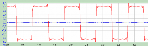
I have just checked with signals similar to the ones you used. With triangle and sine wave the detection threshold was close to 3 Vpeak as expected. With a square wave the peak-peak value of the square wave was lower. There are two explanations for that (in my case):
1. The generator has some overshoot. The generator I used is not particularly good.
2. The filter of the ADC generates ringing, which will be detected as overflow. See the attached picture.
The overflow detection is not done by the ADC (the AK5394A does not have this feature). It is done by the XMOS processor used for the USB interface. It is based on peak values, not an RMS calculation.
So the peak values are sqrt(2) higher than the values on the front.
The peak detection is based on detecting signal levels close to 100%, not necessarily 100% because in some situations you won't reach 100% values, even if you have a strong signal. I plan to make the detection window slightly wider in the next FW release to improve the peak detection.
You should not use the peak detection threshold as a reference.
I have just checked with signals similar to the ones you used. With triangle and sine wave the detection threshold was close to 3 Vpeak as expected. With a square wave the peak-peak value of the square wave was lower. There are two explanations for that (in my case):
1. The generator has some overshoot. The generator I used is not particularly good.
2. The filter of the ADC generates ringing, which will be detected as overflow. See the attached picture.
The overflow detection is not done by the ADC (the AK5394A does not have this feature). It is done by the XMOS processor used for the USB interface. It is based on peak values, not an RMS calculation.
Attachments
So then the voltage levels given on the front plate are correct only for sine signals I guess. Just to be REALLY sure I understand this correctly (sorry for nagging):
Are you referring to "RMS values of a sine signal"? The RMS value will be different for different signal forms, even if their peak-to-peak amplitude is the same.
Again, you are referring to a sine with 1 V-RMS, correct?
Looking at the front panel a bit more I realised I am also confused about the AC switch (seems I am very confused today, sorry for that). What does the AC indicator mean? LED on = "DC filter is on, you get AC only" or LED on = "AC filter is off, you get the full signal with DC"? It's a bit like the red lamp on the coffee machine: does that mean the machine is heating up, or does it mean it's hot and ready to make coffee?
Maybe it would be useful to add this information in the guide document that comes with the instrument.
The values on the front refer to RMS values.
Are you referring to "RMS values of a sine signal"? The RMS value will be different for different signal forms, even if their peak-to-peak amplitude is the same.
So e.g. at the 1 V setting a 1 V sine wave will be equivalent to full scale.
Again, you are referring to a sine with 1 V-RMS, correct?
Looking at the front panel a bit more I realised I am also confused about the AC switch (seems I am very confused today, sorry for that). What does the AC indicator mean? LED on = "DC filter is on, you get AC only" or LED on = "AC filter is off, you get the full signal with DC"? It's a bit like the red lamp on the coffee machine: does that mean the machine is heating up, or does it mean it's hot and ready to make coffee?
Maybe it would be useful to add this information in the guide document that comes with the instrument.
Last edited:
See if you can borrow one for this purpose.
Where is JensH. Other side of the pond from me. Closer to you. It's both your interest.
Cheers,
Just a thought. I just stuck that in there to stimulate the idea.
@Edmond
At the moment other things are more urgent. It could perhaps be interesting to offer DiAna with the RTX6001, but a decision on that is not possible right now.
Actually, I'm more interested Frex project, as his SAR-ADC would be a perfect fit for DiAna, born for each other. Remember, when I starting the project, I did have a SAR-ADC in mind.
Cheers, E.
JensH is the best person to answer, but I suspect it has some sort of root-mean-square detector there.
A sine wave of 1Vrms has 2.8Vpp so overflow triggers at 3.0V makes sense, a triangle wave has less energy so triggers a little later, a square wave has more energy so trigger earlier.
I think this relates to crest factor. Peak to RMS ratio of the waveform.
Actually, I'm more interested Frex project, as his SAR-ADC would be a perfect fit for DiAna, born for each other. Remember, when I starting the project, I did have a SAR-ADC in mind.
Cheers, E.
My preference too. DC to daylight.
We're a bit of T here. Lets take this to your thread.
I got my RTX6001 about a week ago. The performance is very impressive indeed. The noise floor is extremely low, down to -170dBFS.
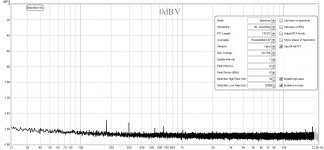
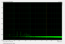
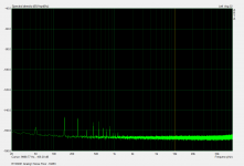
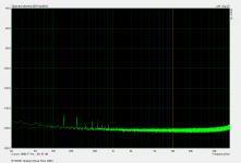
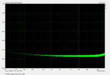
However, with 0dBV, -10dBV, and -20dBV input, there are some spikes (the input is shorted). They look like harmonics of 60Hz, but the amplitude of 60Hz is much lower.
Is there anyone having similar issues?
However, with 0dBV, -10dBV, and -20dBV input, there are some spikes (the input is shorted). They look like harmonics of 60Hz, but the amplitude of 60Hz is much lower.
Is there anyone having similar issues?
Attachments
I guess this is one of the drawbacks of having a low noise floorI got my RTX6001 about a week ago. The performance is very impressive indeed. The noise floor is extremely low, down to -170dBFS.
However, with 0dBV, -10dBV, and -20dBV input, there are some spikes (the input is shorted). They look like harmonics of 60Hz, but the amplitude of 60Hz is much lower.
Is there anyone having similar issues?
")
If you really look for it, some discrete frequencies will show up above the noise floor. The level you have measured seems to be around 50 nV.
These harmonics of the AC supply can be seen on all units, but they are at a level, which shouldn't be a real problem. Most of it seems to come from the power transformer, which does emit some magenetic fields at the harmonics of the 50/60 Hz supply, despite the fact that it is a ring-core transformer.
I have similar mains harmonics in my unit also, at around -145dBV/rtHz.
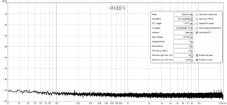
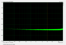
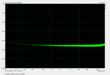
The noise floor is around -168dBV/rtHz (4nV/rtHz) at -20dBV setting, rises to -166dBV/rtHz (5nV/rtHz) at -10dBV setting, both meeting the noise floor spec in the user manual (5nV/rtHz). At 10dBV, the noise floor becomes high enough to hide the mains harmonics, and increases to around -132dBV/rtHz at -30dBV.
ARTA does not allow calibration at 40dBV setting so no measurement for that level.
Attachments
-
 RTX6001 Noise Floor 1 -20dBV.png78.7 KB · Views: 333
 -
 RTX6001 Noise Floor 2 -10dBV.png78.5 KB · Views: 323
 -
 RTX6001 Noise Floor 3 0dBV.png78.3 KB · Views: 144
 -
 RTX6001 Noise Floor 4 10dBV.png78.3 KB · Views: 131
 -
 RTX6001 Noise Floor 5 20dBV.png78.1 KB · Views: 135
 -
 RTX6001 Noise Floor 6 30dBV.png78.2 KB · Views: 138
Up and running
Folks, got my RTX up and running. Very impressed with performance in loop back mode. I’ll post some captures later. The measurements were done with via balanced out to in. Noted left channel residual was higher by 3-4 dB then right. Any suggestions on best method to stim and measure single ended? I have some XLR to BNC adapters but they produced a lot of 60Hz related noise.
Folks, got my RTX up and running. Very impressed with performance in loop back mode. I’ll post some captures later. The measurements were done with via balanced out to in. Noted left channel residual was higher by 3-4 dB then right. Any suggestions on best method to stim and measure single ended? I have some XLR to BNC adapters but they produced a lot of 60Hz related noise.
You are right, the levels of these harmonics are very low, and should not be a real problem. However I still want to try if these can be reduced by installing a cover/shield for the transformer.
Speaks for a 2.5K high grade equipment itself

Saludos B
For what it's worth, I have a fully-loaded R+S UPV and would be happy to assist with any measurements on the RTX - if this is of use. Am in the market for one or two analysers of the RTX type for general sub-assy testing. I would be interested in seeing measurements using the internal PSU - and via an external low-noise PSU. Are there any plans to market the RTX with an option for external powering?
An external power option could be done, but there are currently no plans to offer such an option. With approvals, logistics etc., it is not as easy as it sounds.
If the hum turns out to be a real problem, it could probably be adressed in the commercial version. But I think that in most cases the noise from the connected equipment and cables will be much higher than the internally generated noise.
If the hum turns out to be a real problem, it could probably be adressed in the commercial version. But I think that in most cases the noise from the connected equipment and cables will be much higher than the internally generated noise.
I wasn't suggesting that you develop a dedicated external PSU, with all the various approvals (I know this all too well!), but something along the lines of an external power input. It could be a multi-pin XLR, with a disclaimer, stating the user employ it at their own risk. People can then find out for themselves if their external power option improves noise.
Either way - congratulations on getting the project off the ground!
Where do I find the list price? When are one-off models shipping?
Either way - congratulations on getting the project off the ground!
Where do I find the list price? When are one-off models shipping?
The details regarding exact models and pricing are still TBD.
What do you mean by "one-off models"? Would that be the commercial model?
If so, the shipping dates are also TBD. We will have a limited quatity after the GB units have been shipped, but the next production run has not been started.
What do you mean by "one-off models"? Would that be the commercial model?
If so, the shipping dates are also TBD. We will have a limited quatity after the GB units have been shipped, but the next production run has not been started.
Hi Jens,
I found that the transformer output taps are 9V, 15V, and 15V (3 pairs). I didn't take a close look at the rectifier circuit. Assuming there are three bridge rectifiers, can I just feed the 6pin socket with DC voltages of 12.7V, 21.2V, and 21.2V? I guess the polarity is not important.
Thanks a lot!
Paul
- Home
- Design & Build
- Equipment & Tools
- DIY Audio Analyzer with AK5397/AK5394A and AK4490