I expect the relative error to be greatest in the folding, which it seems is always by hand, so the pitch shouldn't be a real issue. I think that planars require a finer pitched trace since it needs to be artificially lengthened for high enough ohms.
Try the IDE cable method that I mentioned for a quick test, you can draw by hand with rather nice precision.
Try the IDE cable method that I mentioned for a quick test, you can draw by hand with rather nice precision.
I am posting in this forum too:HIFI4ALL Forum: Diy AMT
Here my latest
![URL]](/community/proxy.php?image=http%3A%2F%2F%5BURL%3Dhttp%3A%2F%2Fimg69.imageshack.us%2Fi%2Fdsc02258ah.jpg%2F%5D%5BIMGHTTPDEAD%5Dhttp%3A%2F%2Fimg69.imageshack.us%2Fimg69%2F854%2Fdsc02258ah.jpg%5B%2FIMGHTTPDEAD%5D%5B%2FURL%5D&hash=aa45c1e15cf115be67df99f1f413c0f0)
And messurements too.
![URL]](/community/proxy.php?image=http%3A%2F%2F%5BURL%3Dhttp%3A%2F%2Fimg12.imageshack.us%2Fi%2Fdiy20my38x170mm10cmafst.jpg%2F%5D%5BIMGHTTPDEAD%5Dhttp%3A%2F%2Fimg12.imageshack.us%2Fimg12%2F6278%2Fdiy20my38x170mm10cmafst.jpg%5B%2FIMGHTTPDEAD%5D%5B%2FURL%5D&hash=74ff801a15857dae455a0b92ffade777)
Green is DIY Blue is ESS Heil amt.
Bernt
Here my latest
And messurements too.
Green is DIY Blue is ESS Heil amt.
Bernt
Wow you must be very pleased with yourself. I haven't had a chance to make a diaphragm yet because of my urgent thesis completion, but I have messed around with folding test sheets using cable ties to space the pleats.
Can you share any tips for cutting the aluminium without tears? What is your preferred method? Using water to make it stick to paper seems to help but perhaps there's a better way.
Can you share any tips for cutting the aluminium without tears? What is your preferred method? Using water to make it stick to paper seems to help but perhaps there's a better way.
I am posting in this forum too:HIFI4ALL Forum: Diy AMT
Here my latest
And messurements too.
Green is DIY
Blue is ESS Heil amt.
Bernt
Great work!
Green FR looks good and promising!
My goal is F3 around 300 Hz. If it is achievable with ribbon then it must be achievable with AMT. But longer one.
What are your listening impressions comparing to original AMT?
![URL]](/community/proxy.php?image=http%3A%2F%2F%5BURL%3Dhttp%3A%2F%2Fimg819.imageshack.us%2Fi%2Fdiy20my38x170baffel40cm.jpg%2F%5D%5BIMGDEAD%5Dhttp%3A%2F%2Fimg819.imageshack.us%2Fimg819%2F8952%2Fdiy20my38x170baffel40cm.jpg%5B%2FIMGDEAD%5D%5B%2FURL%5D&hash=c3422640dc7f86030005e3957d8f0118)
Yesterday i was a happy man,mesurements where stunning.
Today...
Red is ESS, blue diy.
Yesteday I mesured at 10cm. distance.
Today at 40cm distance as i usual do,and with a 40cmvide baffel.
Any comments?
I could make a longer AMT,but have to make new tools.
Bernt
I think there is a reason for measurement standards such as 1m x 1m baffle, 1m mic distance, asymmetric driver placement in baffle, etc
")
Since you have all the needed equipment and experience that should not be a problem for you.
Longer AMT- absolutely. I'm thinking to start with 28-30 cm.
its still not bad, just indeed make measurements at 1 m so you wont be disapointed with real results. but also be ware of the room interacting much more so just use it to see really how low it can go, and not so much for the upper frequency response or humps and bumps. also when you see a nsty bump try moving the mic a little to left right front back. to see what happens because it could well be a reflection of some sort. wich has nothing to do with ur driver. outside measurement would be even better. fire it upwards if posible, in a big garden ?
Member
Joined 2003

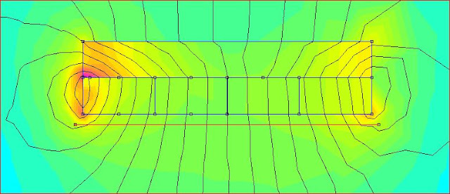
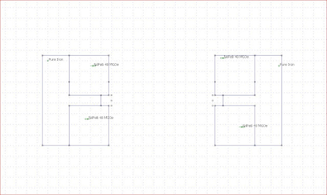
Here is a drawing in femm.shoving magnet polarity:![URL]](/community/proxy.php?image=http%3A%2F%2F%5BURL%3Dhttp%3A%2F%2Fimg685.imageshack.us%2Fi%2Famt1tegn.jpg%2F%5D%5BIMGDEAD%5Dhttp%3A%2F%2Fimg685.imageshack.us%2Fimg685%2F7884%2Famt1tegn.jpg%5B%2FIMGDEAD%5D%5B%2FURL%5D&hash=29f3999d561836cb5a9642823fe8b3ab)
Bernt
I´m experimenting with another magnetic setup for AMTs based on what I´m been working about making bass panels.
So I´d like to correlate your simulation with the one I´ve done on your setup.
I get this field intensity:
Is it more or less what you get?
Exactly the same.I have made some adjustments to get stronger and more liniar field.
![URL]](/community/proxy.php?image=http%3A%2F%2F%5BURL%3Dhttp%3A%2F%2Fimg521.imageshack.us%2Fi%2Famtmagn38mmmembrsimm.jpg%2F%5D%5BIMGDEAD%5Dhttp%3A%2F%2Fimg521.imageshack.us%2Fimg521%2F1356%2Famtmagn38mmmembrsimm.jpg%5B%2FIMGDEAD%5D%5B%2FURL%5D&hash=8bffe6dfa4839cca887355dbef5c428a)
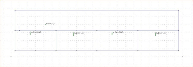
I have used 12x12mm iron.Active diaphragm is 28mm.
![URL]](/community/proxy.php?image=http%3A%2F%2F%5BURL%3Dhttp%3A%2F%2Fimg825.imageshack.us%2Fi%2Famtmagn38mmmembrfieldst.jpg%2F%5D%5BIMGDEAD%5Dhttp%3A%2F%2Fimg825.imageshack.us%2Fimg825%2F1630%2Famtmagn38mmmembrfieldst.jpg%5B%2FIMGDEAD%5D%5B%2FURL%5D&hash=324c80a7de889a7a5282ff23a705405b)
![URL]](/community/proxy.php?image=http%3A%2F%2F%5BURL%3Dhttp%3A%2F%2Fimg560.imageshack.us%2Fi%2Famtmagn38mmmembrdrawing.jpg%2F%5D%5BIMGDEAD%5Dhttp%3A%2F%2Fimg560.imageshack.us%2Fimg560%2F3549%2Famtmagn38mmmembrdrawing.jpg%5B%2FIMGDEAD%5D%5B%2FURL%5D&hash=c0b99ce742ca6c3412424839567de202)
Using 12x12 it is posibly to place the frame between the magnets.Frame, 5x4mm wood, is not on drawing.
Sorry square showing diaphragm is named steel , it has to be air.It affekts mesurements
Bernt,
I have used 12x12mm iron.Active diaphragm is 28mm.
Using 12x12 it is posibly to place the frame between the magnets.Frame, 5x4mm wood, is not on drawing.
Sorry square showing diaphragm is named steel , it has to be air.It affekts mesurements
Bernt,
Last edited:
![URL]](/community/proxy.php?image=http%3A%2F%2F%5BURL%3Dhttp%3A%2F%2Fimg525.imageshack.us%2Fi%2Famt38mmdrawing.jpg%2F%5D%5BIMGDEAD%5Dhttp%3A%2F%2Fimg525.imageshack.us%2Fimg525%2F9306%2Famt38mmdrawing.jpg%5B%2FIMGDEAD%5D%5B%2FURL%5D&hash=187a73b31cd33a90e2eb644e28fd588f)
![URL]](/community/proxy.php?image=http%3A%2F%2F%5BURL%3Dhttp%3A%2F%2Fimg827.imageshack.us%2Fi%2Famt38mmsimm.jpg%2F%5D%5BIMGDEAD%5Dhttp%3A%2F%2Fimg827.imageshack.us%2Fimg827%2F5290%2Famt38mmsimm.jpg%5B%2FIMGDEAD%5D%5B%2FURL%5D&hash=3c4fba11d4b4a382d422e1460c0455c4)
![URL]](/community/proxy.php?image=http%3A%2F%2F%5BURL%3Dhttp%3A%2F%2Fimg248.imageshack.us%2Fi%2Famt38mmfieldstrength.jpg%2F%5D%5BIMGDEAD%5Dhttp%3A%2F%2Fimg248.imageshack.us%2Fimg248%2F8107%2Famt38mmfieldstrength.jpg%5B%2FIMGDEAD%5D%5B%2FURL%5D&hash=0e7562a024d8ea4e9cb709cedd5b79c4)
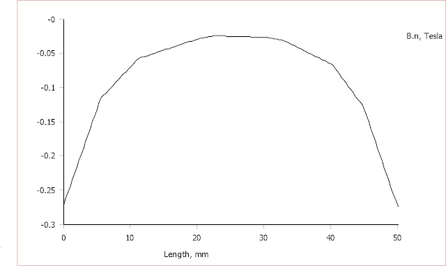
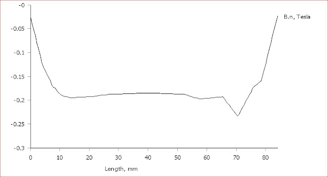
Thanks Bernt! Especially for the last update, it makes more sense with air in the gap and a B.n plot
I understand now that yours is the engine to use.
My idea of using a flat setup for sure has a more linear field, but there is still the back wave to consider.
b.n plot 3 mm in front of magnets:
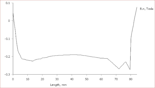
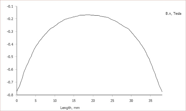
b.n plot 6 mm in front of magnets:
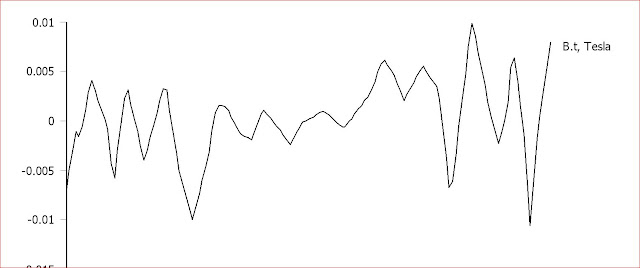
Of course has the b.t field has to be considered as well:

So I guess that configuration goes down the drain.
I understand now that yours is the engine to use.
My idea of using a flat setup for sure has a more linear field, but there is still the back wave to consider.
b.n plot 3 mm in front of magnets:
b.n plot 6 mm in front of magnets:
Of course has the b.t field has to be considered as well:
So I guess that configuration goes down the drain.
Last edited:
Looking at your configuration a little bit, I did this simulation:

The question is if it´s okay with such a large variation over the gap.
That the both sides in a V that produces the soundwave are influonced by slightly different forces doesn´t matter.
Worse is that the soundwaves that are produced in the middle of the gap will have much less amplitude.
b.t field looks well though:
- Status
- This old topic is closed. If you want to reopen this topic, contact a moderator using the "Report Post" button.
- Home
- Loudspeakers
- Planars & Exotics
- Diy AMT