Transformers:
A choice between core geometries can usually be relegated to whichever is easily available.
Toroid cores are popular due to the theoretically lower radiated leakage flux, and wide use in commercial equipment. However, commercial equipment often uses toroidal transformers due to the lower profile and weight as compared to EI or C core transformers. The radiated noise of toroidal transformers can also easily exceed that of EI/C cores, depending on construction quality - there are some indications of this through the sci.electronics archive. As compared to EI/C cores, toroids also have higher interwinding capacitance, lower isolation, and much higher bandwidth. The bandwidth in particular can be a problem, as power line noise is efficiently coupled, whereas an EI core can aid noise filtration. I believe there is a comparison of an Avel-Lindberg toroid and a Magnetek EI in the April '96 Audio Amateur, where the AL toroid was -3db somewhere above 100khz, while the EI managed the same drop at 4khz.
EI cores have the disadvantage when it comes to size, weight, and potential radiated leakage flux. However, a well designed EI will have a copper band surrounding the windings to act as a shorted turn for the leakage flux - radiated noise will usually drop to negligible levels. Keep in mind that many well-reviewed amps in the past have been built with EI core transformers - the quality of construction is of more importance than the physical geometry of the transformer.
Keep in mind that it's also simple enough to lower noise in the best way possible - keep the power supply magnetics shielded in a separate enclosure physically distanced from other electronics.
Plitron is a good quality toroid manufacterer, along with Avel-Lindberg - but do consider that you could potentially spend 5x the cost on the toroids for 0.5x the power capability of other transformers. The difference in cost could easily be spent with higher returns on other parts of the audio system, especially important in tight budget situations.
Rectifier layout and power supply design:
Time for some reading...Rod Elliot has an article available online on power supply design:
Elliot Sound Products - Linear Power Supply Design
-Nikhil
Edit - ESP link...
forgive my newbieness .. but how does that look like?
i'm not too good w/ this .. this is my first REAL diy project (last was a complete kit with full instructions) ..
that is speaking for 2 torroids right? one for each channel?
edit: just saw that last post, will read through it .. but i'd still love a diagram")
i'm not too good w/ this .. this is my first REAL diy project (last was a complete kit with full instructions) ..
that is speaking for 2 torroids right? one for each channel?
edit: just saw that last post, will read through it .. but i'd still love a diagram
Peter, good advice. I think eLizard wants to go the monoblock route but your single PSU chassis and single amp chassis is something he might consider.
eLizard,
How about it? Have you seen Peters Gainclone pics?
If you look at posts 57-63of the big gain clone thread there are some pictures of Peter's amp that he is now selling in a limited run to some really lucky customers. It is a design you might consider. You will save money buying one large toroid instead of two smaller ones. Check the link below. It is the Thor Amp and the power supply in that schematic is the type one I described above. Use that schematic minus the 1uF cap in red, and the RC circuit (connect pin7 straight to the star ground), follow the tips and pics Peter, BrianGT, Fedde, Fred, planet10, carlmart and several others have posted and you'll have a winner. Pay particular attention to the pics of people chip layouts, specifically the very short lead distances. Try an open air prototype first before you cut on your cases.http://home.student.utwente.nl/f.s.bouwman/audio/images/invertedLM3875.gif
elizard:
Nearly forgotten - TNT-Audio also has a power supply design article:
http://www.tnt-audio.com/clinica/ssps1_e.html
There are a few types of topologies given, such as:
As far as the Outlaw amp...take a look through the BPA-200 application note from National. Four LM3886 chips in a bridge/parallel configuration could potentially allow for 170-200w into an 8 ohm load, with 0.02% THD. Parallel more chips and power output could keep up into 2 ohm loads (given enough chips to distribute current, 800w), if you have such ghastly drivers. Parallel enough of the chips, and you could start thinking about driving an arc welder. Ease of use would be the prime selling point of using LM3886 chips at this power level, as discrete components could accomplish the same at lower cost (though considering the cost of pre-matched transistor pairs...perhaps not...).
-Nikhil
Ok, well then, some more changes
Thank you philo.
How does a 400VA torroid with 22V secondaries sound? That one runs for $72 at plitron (canadian funds!)
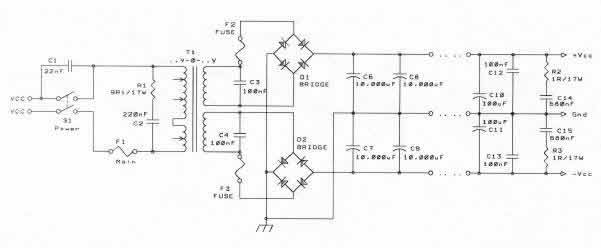
Also, for the PS schematic I was looking at someone elses that they used for their gaineclone .. or was it for peters? in either case, here it is .. would this work?
oh .. and there was somewhere i read about the torroid having to be dual primary? (does that make sense?) are the standard ones from plitron the ones i want? or do i have to make a special request?
Thank you philo.
How does a 400VA torroid with 22V secondaries sound? That one runs for $72 at plitron (canadian funds!)
Also, for the PS schematic I was looking at someone elses that they used for their gaineclone .. or was it for peters? in either case, here it is .. would this work?
oh .. and there was somewhere i read about the torroid having to be dual primary? (does that make sense?) are the standard ones from plitron the ones i want? or do i have to make a special request?
Attachments
Thats Peter's amp alright. It was nicely drawn up by one of the other members of the forum. After some advice by Peter he redrew it and posted far down in the thread. Use either with your 400VA toroid and your good to go...
The website Nikhil suggested has a lot of good stuff on it and is worth reading through. There is stuff on just about any DIY audio topic you care to read about. Good stuff.
The website Nikhil suggested has a lot of good stuff on it and is worth reading through. There is stuff on just about any DIY audio topic you care to read about. Good stuff.
Standard Plitron comes with 2 separate secondaries. Run grounds separately and connect them only at the amp's filter caps. One toroid works pretty good with two channels and I think it might be even a better choice than using two smaller separate transformers for ea. channel. It's cheaper too
That depends on how much you trust your transformer, soldering skills and schematic reading ability Just kidding, but the first is reason is for real. I only use a single fuse on the primary input of the amp and most others do for their Gainclones as well. In a much more expensive amp with more to lose with a transformer short it is a good idea, along with other protection features such as a speaker protection circuit. Fuses can be a source of RFI but using a separate PSU with your amp reduces the factor. I would say it is up to you, but your really only protecting a $5 IC. Significantly less expensive than a bank of TO3 transistors.
As for the rating, I use a 7 amp right now. when I started testing at low levels I used a 3 amp, which blew when I accidently dropped a meter prode into the circuit. After I was sure of my system, I switched to a 5 amp fuse which blew when I hooked the amp to my father's ESS speakers and turned up the volume.
So far, the 7 amp fuse has worked well.
Just kidding, but the first is reason is for real. I only use a single fuse on the primary input of the amp and most others do for their Gainclones as well. In a much more expensive amp with more to lose with a transformer short it is a good idea, along with other protection features such as a speaker protection circuit. Fuses can be a source of RFI but using a separate PSU with your amp reduces the factor. I would say it is up to you, but your really only protecting a $5 IC. Significantly less expensive than a bank of TO3 transistors. As for the rating, I use a 7 amp right now. when I started testing at low levels I used a 3 amp, which blew when I accidently dropped a meter prode into the circuit. After I was sure of my system, I switched to a 5 amp fuse which blew when I hooked the amp to my father's ESS speakers and turned up the volume.
So far, the 7 amp fuse has worked well.
Fuse to protect transformer
The fuses between the transformer and the bridge rectifier are to ptotect the transformer if the bridge fails and forms a short. This may be an unlikely event but both the the fuses and the bridge rectifier are quite cheap and can be replaced with only a drive to Radio Shack. The transformer is expensive and it may take a month to order a replacement.
The fuses between the transformer and the bridge rectifier are to ptotect the transformer if the bridge fails and forms a short. This may be an unlikely event but both the the fuses and the bridge rectifier are quite cheap and can be replaced with only a drive to Radio Shack. The transformer is expensive and it may take a month to order a replacement.
I don't know if you ever had a bridge failure, but I had on more than few occasions and a fuse on primary always managed to protect a transformer. I also believe, that speakers are usually more expensive than a transformer.
When you use one bridge for pos and neg rails, the fuses between transformer and bridges in case of bridge failure cut off both rails. But in a case of two separate bridges, it cuts only one rail and you effectively have one rail working, the other not. Depending on amp, this will produce DC voltage at the speakers.
In case of a fuse at primary only, in case of one bridge failing, both rails are cut off and the speakers are safe.
.When you use one bridge for pos and neg rails, the fuses between transformer and bridges in case of bridge failure cut off both rails. But in a case of two separate bridges, it cuts only one rail and you effectively have one rail working, the other not. Depending on amp, this will produce DC voltage at the speakers.
In case of a fuse at primary only, in case of one bridge failing, both rails are cut off and the speakers are safe.
ok, here's another one ..
i'll need to build a temporary speaker protection circuit .. do i just use a simple resistor (i think i read about this one somewhere ..) or do i actually have to build some elaborate thing ..
i'll just want a protection circuit the first couple times i power up the gainclone ..
i'll need to build a temporary speaker protection circuit .. do i just use a simple resistor (i think i read about this one somewhere ..) or do i actually have to build some elaborate thing ..
i'll just want a protection circuit the first couple times i power up the gainclone ..
Most real speaker protection circuits are more complicated than this entire amp. A resistor is not going to stop DC from reaching your speakers. I just use a an old speaker, a bare unenclosed one would work fine as well and use it as a tester. If you double check your setup, you should be fine. I cut away all the unused pins on the IC so it is much easier to solder the right pins. If it plays without any noticable distortion, you can go ahead and use a better speaker to listen for any ground loop hum or oscillation.
elizard said:ok, here's another one ..
i'll need to build a temporary speaker protection circuit .. do i just use a simple resistor (i think i read about this one somewhere ..) or do i actually have to build some elaborate thing ..
i'll just want a protection circuit the first couple times i power up the gainclone ..
If you 'll wire everything correctly you will have no problems. When I run the amp for the first time I only check the DC offset after power up. If it's les than 50mV it usually means the amp should work fine. Use crappy speaker in the beginning and coupling cap at the input.
oh yeah, forgot to ask
for internal wiring, what gauge wire should i use?
is 20 gauge good enough? or should i go higher?
also peter, how do you make the cable that goes from the power supply into the gainclones?
i was thinking 3 twisted strands (in some heatshrink tubing) .. does that sound sensible, or should i try something else? also what gauge for that cabling?
- Status
- This old topic is closed. If you want to reopen this topic, contact a moderator using the "Report Post" button.
- Home
- Amplifiers
- Chip Amps
- DIY Amplifier Suggestions - on a tight budget