Instead of a fixed resistor try using an NTC between the amp outputs and the transformers. For my 3 phase Papst motor setup I'm using NTC 5D-9 devices, these have a cold resistance of 5 ohms, but only drop 0.5V when hot. The Premotec motors draw a lot less current so a smaller NTC might be better. The only downside is that if you switch off it takes a few seconds for the resistor to drop in temperature before the resistance is high enough to allow a restart.
An alternative solution is to use fixed resistors and a timer relay to short them out when the startup current has dropped.
An alternative solution is to use fixed resistors and a timer relay to short them out when the startup current has dropped.
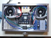
Fired it up for the first time - after adjusting pots I’ve got ~113VAC unloaded for both 0 and 90. Next step is testing with a spare Hurst motor.
Thanks for making this possible, Bill.
Thanks for making this possible, Bill.
Attachments
Last edited:
Hi Pyramid,
Would you mind explaining a bit about the design of the buffers at the output? I'm no pro and am a little befuddled by e.g. R7,8 and C7,8. I wouldn't mind a complete overview but my main question is: why have C7 at all and why place the return node of C7 between the two resistors?
Thanks,
Conner
Would you mind explaining a bit about the design of the buffers at the output? I'm no pro and am a little befuddled by e.g. R7,8 and C7,8. I wouldn't mind a complete overview but my main question is: why have C7 at all and why place the return node of C7 between the two resistors?
Thanks,
Conner
Hi Pyramid,
Would you mind explaining a bit about the design of the buffers at the output? I'm no pro and am a little befuddled by e.g. R7,8 and C7,8. I wouldn't mind a complete overview but my main question is: why have C7 at all and why place the return node of C7 between the two resistors?
Thanks,
Conner
U2A-U2D are classic Sallen-Key low pass filters; the LPFs are needed because the output of the inverters (and the uP) are PWM with 5VPP 18kHz squarewaves of variable duty cycle. When you LPF the PWM signal, it will produce the average voltage of the duty cycle which is an analog sinewave in this case.
The Fc of the LPF circuits used is: 1/(2Pi*SQRT(R7*R8*C7*C8)) or ~225Hz in this case. Because there are 2 poles (C7 & C8), the slope of the stopband is -12dB per octave (-40dB per decade). The response of the passband and the transition (corner) is determined by the ratio of C7 and C8. The damping factor of the filter is: α=2*SQRT(C7/C8) and for a butterworth response we want critical damping or α=1.414, so C7 needs to be half the size of C8. A butterworth filter has a maximally flat passband. I used standard values for caps that give an α=1.368, so it is just slightly underdamped.
The inverters are needed between the µP and the LPFs because the port pins of the µP can drive the outputs to a hard low, but have pull up resistors for the high output state and cannot drive much of a load high. The output of the inverters can drive their outputs both high and low.
The design equations for a Sallen-Key filter are beyond the scope of a DIY discussion, but you can find the complete derivations in a book available on-line if interested further: Design of Active Filters with Experiments by Howard M. Berlin, Appendix B page 211.
Last edited:
U2A-U2D are classic Sallen-Key low pass filters; the LPFs are needed because the output of the inverters (and the uP) are PWM with 5VPP 18kHz squarewaves of variable duty cycle. When you LPF the PWM signal, it will produce the average voltage of the duty cycle which is an analog sinewave in this case.
The Fc of the LPF circuits used is: 1/(2Pi*SQRT(R7*R8*C7*C8)) or ~225Hz in this case. Because there are 2 poles (C7 & C8), the slope of the stopband is -12dB per octave (-40dB per decade). The response of the passband and the transition (corner) is determined by the ratio of C7 and C8. The damping factor of the filter is: α=2*SQRT(C7/C8) and for a butterworth response we want critical damping or α=1.414, so C7 needs to be half the size of C8. A butterworth filter has a maximally flat passband. I used standard values for caps that give an α=1.368, so it is just slightly underdamped.
The inverters are needed between the µP and the LPFs because the port pins of the µP can drive the outputs to a hard low, but have pull up resistors for the high output state and cannot drive much of a load high. The output of the inverters can drive their outputs both high and low.
The design equations for a Sallen-Key filter are beyond the scope of a DIY discussion, but you can find the complete derivations in a book available on-line if interested further: Design of Active Filters with Experiments by Howard M. Berlin, Appendix B page 211.
That is exactly what I was looking for. Thank you! I wondered why you ran a low-pass, because most resources I see on BLDC drivers mention 40kHz+ but that is with the final voltage being generated directly at the mosfets, not running through an amplifier, which will have it's own frequency response. How did you decide on 18kHz? It seems pretty arbitrary to me.
And now that I know the name of the topology is Sallen-Key, I can actually learn about it. I have seen it mentioned many times and even glanced over it roughly once or twice, but haven't studied it in detail. I guess that is the benefit of learning this stuff in school/doing it for a living-- all those classics are burned into your memory and stick out like sore thumbs when you see them.
Thanks so much.
That is exactly what I was looking for. Thank you! I wondered why you ran a low-pass, because most resources I see on BLDC drivers mention 40kHz+ but that is with the final voltage being generated directly at the mosfets, not running through an amplifier, which will have it's own frequency response. How did you decide on 18kHz? It seems pretty arbitrary to me.
Most of the PWM motor controllers use the motor windings and rotor inertia as the LPF, but that can produce a lot of EMI, not good near a phono pickup (The VPI HW-40 direct drive does exactly this; 36VPP 10kHz squarewaves directly into the motor with no filtering, directly under the platter!). PWM amps are class D so they are efficient, which is important for high power motors, but even simple LC filters on the output can drastically reduce the amount of radiated EMI. The MA-3D is a good example of this.
The 18kHz PWM frequency is a function of the µP and how it accomplishes PWM. The clock signal used for the PWM comparator is the crystal frequency/1024 or in this case: 18.432MHz/1024. With the 2 pole filter, the 18kHz PWM signal is attenuated ~-76dB, so 5VPP becomes 0.8mV.

You must not have searched too hard - I found this on my first try (though I have a working speed controller, so I’ve previously, and successfully, found, ordered and implemented a compatible substitute):Good afternoon, Mr. Carlin,
The MAXIM D51833-10+ is OBSOLETE at MOUSER.
Is there a replacement part?
Sure hope so.
Searched the thread and found nothing.
Thanks and take care,
https://www.diyaudio.com/forums/ana...tor-turntable-motor-drive-83.html#post5902466
Perhaps I’ve misread the tone of your post, but it’s not Bill’s job to keep years-old BOMs up to date for the several fully-realized products he has selflessly donated to the community - not to mention the countless hours and posts he’s given in support of them.
If you had ordered a motor a few days ago I suspect you would hope a replacement was available, too.
I searched the thread with the DIYAudio search function and it said no results.
When I first went through the posts weeks ago I should have made more notes.
I hope I am misreading the tone of your post since you seem to be affected with PRINCESS AND THE PEA syndrome - if you thought I was being demanding or expecting the unexpectable. I just asked a question with the hopes I would not have to ask ANAHEIM AUTOMATION if I could return the motor.
I purchased an EAGLE and a ROAD RUNNER from PHOENIX so i have a great appreciation for Mr. Carlin's work and would gladly pay a licensing fee to use this motor system. I do not think this puts me in the greedy boy category.
I do greatly appreciate your pointing out the replacement part post.
If this is to remain a continuing project, as it should, it might be nice if that link was part of post #1.
Mr. Carlin's willingness to help folks is unequalled.
First, does anyone have a spare board for this project? Also looking for an SG4 board, but I will cross post there. Of course I can (and have) order from Oshpark, but it benefits both parties if someone is looking to unload unneeded extras.
Second, I’d like to apologize to rickmcinnis for my undeservedly harsh and unwarranted reply to his post above. As I revisit these various threads it is clear that he has nothing but respect and praise for Pyramid’s generosity with his time and knowledge - a sentiment I certainly share.
Second, I’d like to apologize to rickmcinnis for my undeservedly harsh and unwarranted reply to his post above. As I revisit these various threads it is clear that he has nothing but respect and praise for Pyramid’s generosity with his time and knowledge - a sentiment I certainly share.
- Home
- Source & Line
- Analogue Source
- DIY 4 Phase Sinewave Generator for Turntable Motor Drive