C3 is a pretty decoupling critical capacitor. (What is it's value and the resistor feeding it?) Something to consider is an RC decoupling network on the power to the primary of T1.
Do you have a scope?
The designer apparently likes transformer coupling. I do a lot of IT based designs, but I only use a single interstage and either avoid another stage altogether or use RC coupling between stages.
You have not changed the values of the cathode bypass caps?
Note that the first and third stage are in phase and LF coupling from the output back to the input is in phase, provided there is sufficient gain oscillation will be the result. Additional decoupling specifically for the first stage might improve the stability margin.
schema
ok, hope you have as much fun reading it as I had drawing it!
V1 = JAN-CHS Sylvania 6sn7w short bottle, chrome top, green label.
V2 = Sylvania 5687 Gold Brand
V3 = any nice 2a3
V4 = GZ37
V5 = EZ81
L1 = 5H, 26 DCR
L2 = 10 H, 53 DCR
C1 = 50uf ASC oil
C2 = 200uf WKZ 550V
C3 = 150uF 350V
C4 = 2200uf
C5 = 470uF
C6 = 100uF
R2 = 887ohm
R3 = 560ohm
R4 = 5.35k
T1 = LL1660 DCR about 1060ohm
T2 = NC20 DCR about 470ohm
T3 = XE20S DCR about 110ohm
T4 = Hammond 302ax
T5 = Hammond 261C6, choke, 30uf ASC oil, 100uf (from memory)
I understand all comments 'n opinions.. (btw, I'm the designer). I'm having fun with my first try on here thus far! Honestly, my intention first is to get a better understanding of an interesting phenomenon from some skilled folks on here. After such, I'd be happy to engage 'why did you' and 'how did you end up with' discussions!
More info... when I replaced the 200uf black gate.. I replaced it with 200uf Xicon. Also, when the circuit was in oscillating condition, I switched the polarity of the NC20 secondary, and on power-up, it went into a higher pitched oscillation that was so nasty in amplitude, I didn't try to measure it! (speaker cone was going to launch across the room).. and later abandoned the amp. I've since rebuilt the amp with additional power supplies, and the performance is lackluster. (admittedly, I could have looked further with a dummy load, but I didn't).
The sn7 stage is there for tone almost as much as it's there for gain. The 5687, for drive. I've tried so many tubes in replace of the 5687, and all of them were boring. For example, 71a... sweet mids and highs.. the LF was somewhat muddy and soft. -If there is one way I can describe this topology.. it's more gain than I want. Honestly. But what it does.. is takes the beautiful tone of the sn7, and shoves it up the wazoo into the 2a3, and the LF result is impressive. The mid on up is a bit stressed sounding.. but I digress.
Last edited:
@AJT.. let me say first, I've used diyAudio for reference for many years, and I have respect for the members from which I've gained knowledge and direction. It's thrilling for me to have interest from members of this forum on work of which I have spent much time.
My design, is at heart, the result of a hobby. A number of years ago, I started with copying a 6sl7 SRPP schema.. Then, about every use of a sn7 front end you can imagine. (Cascade, Cascode, Direct Couple, C couple, TX couple).. Eventually, when buying (spending $$) on IT's, it was recommended to me.. go from 2 to 3 stage designs.. as a driver for a 2a3 (sn7 was suggested to be an inadequate driver for a 2a3). After spending time on this suggestion, it proved promising. Long story short, a combination of parts at hand, one circuit leading to the next, and experience implementing them, I ended up with the circuit at hand.
My design, is at heart, the result of a hobby. A number of years ago, I started with copying a 6sl7 SRPP schema.. Then, about every use of a sn7 front end you can imagine. (Cascade, Cascode, Direct Couple, C couple, TX couple).. Eventually, when buying (spending $$) on IT's, it was recommended to me.. go from 2 to 3 stage designs.. as a driver for a 2a3 (sn7 was suggested to be an inadequate driver for a 2a3). After spending time on this suggestion, it proved promising. Long story short, a combination of parts at hand, one circuit leading to the next, and experience implementing them, I ended up with the circuit at hand.
> schematic
A nice sketch and fine plan except for one thing.
"NEVER"(*) run more than two gain stages on one B+ decoupling node!!
As said, "you might have built a phase shift oscillator". With R-C coupled stages you are pretty sure to have an oscillator, unless your B+ filtering time constants are absurdly longer than your audio coupling time constants. Transformer coupling is different, and you might change your motoboat rate by flipping some windings. But there is really no good reason to run your small tubes on the same node as your big tube.
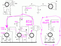
Especially odd that V2 is decoupled and V1 (more sensitive) is not.
See pictures. One obvious fix is to add decoupling on V1. First pic.
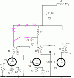
Duh! The decoupling for V2 can power the V1 stage also! Second pic. This meets the "no more than two stages" rule of thumb. There will be more voltage drop in R4, but V1 current is probably small compared to V2 current? If DC Voltage is really critical, make R4 say 4K or 3K. C3 is stunningly large at 150uFd so will be fine even with somewhat smaller R4.
(*) There are exceptions. Large loss networks between stages. Fully differential stages. Hyper solid (usually active) power supplies. When you find an experienced designer "violating the rule", assume this was carefully thought out and will work. But in your own work, until you have got your feet wet with lots of motoboating amps, 2-per-node is a safe guide.
A nice sketch and fine plan except for one thing.
"NEVER"(*) run more than two gain stages on one B+ decoupling node!!
As said, "you might have built a phase shift oscillator". With R-C coupled stages you are pretty sure to have an oscillator, unless your B+ filtering time constants are absurdly longer than your audio coupling time constants. Transformer coupling is different, and you might change your motoboat rate by flipping some windings. But there is really no good reason to run your small tubes on the same node as your big tube.
Especially odd that V2 is decoupled and V1 (more sensitive) is not.
See pictures. One obvious fix is to add decoupling on V1. First pic.
Duh! The decoupling for V2 can power the V1 stage also! Second pic. This meets the "no more than two stages" rule of thumb. There will be more voltage drop in R4, but V1 current is probably small compared to V2 current? If DC Voltage is really critical, make R4 say 4K or 3K. C3 is stunningly large at 150uFd so will be fine even with somewhat smaller R4.
(*) There are exceptions. Large loss networks between stages. Fully differential stages. Hyper solid (usually active) power supplies. When you find an experienced designer "violating the rule", assume this was carefully thought out and will work. But in your own work, until you have got your feet wet with lots of motoboating amps, 2-per-node is a safe guide.
Attachments
Last edited:
@AJT.. let me say first, I've used diyAudio for reference for many years, and I have respect for the members from which I've gained knowledge and direction. It's thrilling for me to have interest from members of this forum on work of which I have spent much time.
My design, is at heart, the result of a hobby. A number of years ago, I started with copying a 6sl7 SRPP schema.. Then, about every use of a sn7 front end you can imagine. (Cascade, Cascode, Direct Couple, C couple, TX couple).. Eventually, when buying (spending $$) on IT's, it was recommended to me.. go from 2 to 3 stage designs.. as a driver for a 2a3 (sn7 was suggested to be an inadequate driver for a 2a3). After spending time on this suggestion, it proved promising. Long story short, a combination of parts at hand, one circuit leading to the next, and experience implementing them, I ended up with the circuit at hand.
still unclear to me why you wanted three stages of gain....
you do understand that the gain of the previous stage is amplified
by the succeeding stage right?
what input sensitivity were you going after?
i too am a learner here, and i learned so many things reading the postings of PRR and a lot of other learned members, do check them out when you have the time....
j8ke1,
Thanks for taking the trouble to draw the schematic, and to list the parts values.
With that, you have already received a couple of good hints of how to fix the amp.
I am pretty sure you will be able to get the amp up and running without oscillation.
I do not remember if it was already mentioned earlier in this thread, the spacing and orientation of the 2 interstage transformers, and the output transformer is important.
Otherwise you might get some magnetic coupling between stages.
I do not think it is the cause of oscillation in your case (the lack of first stage decoupling is more likely).
However, it might be possible that an otherwise marginal coupling which would not cause oscillations, could instead change the frequency response and distortion characteristics of the amp.
> why you wanted three stages of gain....
Draw it in the dirt.
2A3 is a VERY low-gain tube. Probably needs 60V of drive, maybe more.
5687 is kinda a big 12AU7, low-ish Mu, near 17.
The transformers could be step-up or step down. When tubes cost real money, we used step-up to add voltage gain. But frequency response suffers. I do not know what ratios these are. I would pencil "unity", and assume the tube gets "most" of its Mu as voltage gain. Then the input of V2 needs about 60V/17 or 3.5V.
Power amps commonly have sensitivities nearer 1V.
I am not sure he needs all the gain of a 6SN7 (about another 15). A gain of 2 might do. In R-C coupled we might omit cathode caps to drop gain in both V1 and V2. That raises plate resistance and that is bad with transformers.
He could use carefully custom transformers and a V2 of VERY high Gm to get the gain without a high plate node impedance and transformer troubles. This seems to lead to rarer microwave tubes, but at high current, more complication for the winder.
Or he could cascade the gain over two popular-price tubes. (6SN7 used to be 33 cents....) It does mean another transformer. Obviously he likes iron, so no problem there.
Many ways to skin this cat. I don't think two triodes in front of 2A3 is excessive. _I_ do think two interstage irons is excessive, but that is a matter of taste (and where you want your wealth).
But some things are not open to taste. Amplifiers make small signals into big signals. Big signals *sneak back* through a common power supply. The main cap is low impedance in the audio band but high impedance for sub-sonic. Doesn't damp the sneak-back. The amplifier does not amplify very sub-sonic. So we very typically have a few-Hz putt-putt motor-boat oscillation. Sometimes full power, and sometimes barely able to damage a speaker.
Sneak-back in two R-C coupled stages is negative feedback. "Can't oscillate".
Sneak-back in three R-C coupled stages is positive feedback
. "WILL oscillate!" In theory it has to meet Nyquest's Criteria. In practice, Murphy finds a way. If you get lucky at first, then Murphy makes parts drift until it putt-putts.
Last edited:
It's his design, and if he needs the gain, then yes 3 stages is OK. Not my choice or yours. The OP has already stated this design was the result of experimentation to find what he likes best. No one else has to like it or agree that it is an optimum solution. We can however propose how to eliminate the positive feedback issue in this design.
Many of the unquestionably popular SE amp designs are 3 stages - in particular the JE Labs stuff everyone seems to like to copy.
I'm on another planet, my line stages have a single tube and output transformer, power amps are no more than 2 stages. So you know I don't disagree with you AJT..
Many of the unquestionably popular SE amp designs are 3 stages - in particular the JE Labs stuff everyone seems to like to copy.
I'm on another planet, my line stages have a single tube and output transformer, power amps are no more than 2 stages. So you know I don't disagree with you AJT..
In the schematics below I can see a transformer coupled stages. High mu triodes and signal pentodes are not recommended for this kind of services because of its high plate resistance. In other term, there may be coupling between stages by means of the stray fields around the transformers, which can cause oscillations.
"The main cap is low impedance in the audio band but high impedance for sub-sonic. Doesn't damp the sneak-back. The amplifier does not amplify very sub-sonic. So we very typically have a few-Hz putt-putt motor-boat oscillation."
This is as close to answering the question for which I've started this thread. For the moment, I'd like to understand it, even more than I care about fixing it. (I'm leaning towards a comment I made earlier about the bandwidth of the amp versus the bandwidth of the supply)
"the hows and whys of tube circuits, those excite me more..... "
Yes! Exactly!
"my line stages have a single tube and output transformer, power amps are no more than 2 stages."
Hey, that's like, kind-of what I'm doing?! (but a a little different. -joking)
Perhaps at this point, I need a CAD package in order to get the full understanding of this phenomenon that I'm looking for.
Turning to the 'implementation' side of this conversation.. My first several years of trying circuits in front of a 2a3, were all two stage designs. SN7, SL7, 5687, 12au7, 5842, 6072a; SRPP, cascade, paralleled, front end with CF, direct coupled, cap coupled, different biasing...
And at some point, I decided I was fond of the tone of a 6sn7. BUT, it simply isn't a low Rp tube, suitable for directly driving a 2a3. Hence, the move to three stage designs.
I mentioned earlier in this thread, that I tried this exact amp with a 71a in place of my 'V2' driver tube. There, I'd think the all the focus on gain would subside, as that amp had a voltage gain of 60ish. It was a smooth sound, but the bass lacked extension, wasn't dynamic, nor exciting to listen to. So, I tried 12b4a. Sigh.. NEXT!
I don't need or even want the gain I have here. The thing this amp does, that you aren't seeing on paper, is have the nice tone of the sn7, with the huevos of the 5687. Actually, a pretty even combination of the two.
Can anyone suggest a lower gain tube that would have the 'drive' I'm getting from the 5687? I'll try it! For some reason (someone tell my why), the 5687 is crazy good as a 'driver'. (perveance?)
Perhaps at this point, I need a CAD package in order to get the full understanding of this phenomenon that I'm looking for.
believe me, this board is the best forum there is....
all my tube learning were from this site, i used to read books
but the theory sometimes are over my head, but reading posts here
made me understand the concepts better....
- Status
- This old topic is closed. If you want to reopen this topic, contact a moderator using the "Report Post" button.
- Home
- Amplifiers
- Tubes / Valves
- DIY 2a3SE oscillation question!