The HELP file tells all. ") Is there something specific in it you're having trouble with?
Is there something specific in it you're having trouble with?
Not AFAIK.
WRT THs, HR sims have proven to be accurate enough to show a performance trend if accurate driver specs are used and a good job was done to preserve the area expansion throughout its length with the understanding that where the WLs are large WRT horn area, preserving it through the bends isn't required, which considering this one's size at an 80 Hz XO point means it's not an issue at all. Indeed, the discontinuous bends will act as a low pass filter to attenuate some of its out of BW HF response.
That said, based on others TH, TP build results, this particular alignment is acoustically large enough to in theory measure somewhat smoother overall than predicted if the driver's specs are accurate, so combined with its 'wrong' bends and relatively high acoustic loading it may not require any of the TL centric stuffing many others require unless it tends to sound a bit hollow.
GM
Is there something specific in it you're having trouble with?Not AFAIK.
WRT THs, HR sims have proven to be accurate enough to show a performance trend if accurate driver specs are used and a good job was done to preserve the area expansion throughout its length with the understanding that where the WLs are large WRT horn area, preserving it through the bends isn't required, which considering this one's size at an 80 Hz XO point means it's not an issue at all. Indeed, the discontinuous bends will act as a low pass filter to attenuate some of its out of BW HF response.
That said, based on others TH, TP build results, this particular alignment is acoustically large enough to in theory measure somewhat smoother overall than predicted if the driver's specs are accurate, so combined with its 'wrong' bends and relatively high acoustic loading it may not require any of the TL centric stuffing many others require unless it tends to sound a bit hollow.
GM
I finished the model, but I am a bit skeptical, is it correct? for the driver that big the horn looks pretty thin... Its a google sketchup model, (you can get sketch up free from google) and I have added dimensions to it...please evaluate to be sure that I understood hornresp correctly...
Attachments
Gees, what a hassle! I had to load the current version of it and apparently you can't load a newer version on top of an existing one without then running its repair program.
Regardless, all I saw was a long rectangular bar with some mostly unreadable numbers jumbled all together at each end, so don't know what you drew, but it doesn't look like a TH which must be folded back on itself. Anyway, look at some of the existing builds along with the various folding schemes if you're confused as to what it should look like before trying again.
GM
Ok
That box is big.
Sub 686.375 Lt internal is going to be over 700 external.
I wouldn't use the Lab 12 to begin with unless you already own it. It will be better in a FLH or a reflex cab.
Which to note I just finished 2 reflex cabs
for a set of Lab 12's I bought to experiment with for TH designs. The boxes are 30x15x18. and do 30-Hz up to 500. Though the driver itself isn't designed for that.
At roughly $120-125 a pop I don't think the Lab 12 will be considered cheap.
Honestly you should take a bit to read the main TH thread within this subwoofer section. There are numerous plans for different drivers.
http://www.diyaudio.com/forums/showthread.php?t=97674
Honestly you should take a bit to read the main TH thread within this subwoofer section. There are numerous plans for different drivers.
http://www.diyaudio.com/forums/showthread.php?t=97674
The previously linked thread I have been dwelling on for quite some time now and I haven't even reached a quarter of the way there. Its tooo long, but from skimming through it, I found that the AV12, Rythmik, B&C but the drivers that are recommended are over $200 USD, I live in Canada and shipping here is 1/2 the price of the drivers themselves. However, I do hear a lot of thought of multiple drivers in a single tapped horn. How do I go about doing that in HornResp? Is there a special selection in the menu? I am going to try to model a tapped horn by using the drivers from the SPUD clone (I think the drivers were dual W8-740)...
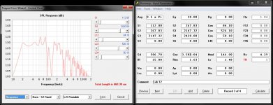
Yay!!!, I guess I will get right on it, after I buy some tools...This might take some time (time scale in months) so please bear with me cause I am in University, doing such builds require some cash (whch I am short of at the moment). But not to worry, I will figure something out. But I am curious as to the "Eg" value, is that correct?
Attachments

Last edited:
The "Eg" value needs to be either 400W at 6 Ohms or 400W at 8 Ohms...
I am confused about the measurements. I need help. If I were not to fold the horn and just lay it out with a height of 13" (330.2 mm) to accommodate the driver and calculate the appropriate areas, the mouth of the horn ends up to be just 73.29 mm wide at 330.2 mm high...What? This doesn't make sense...
I am confused about the measurements. I need help. If I were not to fold the horn and just lay it out with a height of 13" (330.2 mm) to accommodate the driver and calculate the appropriate areas, the mouth of the horn ends up to be just 73.29 mm wide at 330.2 mm high...What? This doesn't make sense...
The voltage value (e.g.) in theory should be however much is required to reach Xmax and/or the driver's short term power rating, whichever is lower. The Lab12 has a 13 mm Xmax, so in theory it's limited to ~23 V and since it's nominally a 6 ohm driver all you need is 23^2/6 = 88.17 W. to hit ~125 dB/20 Hz/m when corner loaded.
In reality, THs can handle a bit more power than predicted, so I'd want at least 150 W on tap.
??? You have to fold it at least once.
?? The sim is in cm, so you need to convert its dims to mm if you want to use mm. Now the terminus's width becomes 10x longer at ~732.9 mm.
GM
In reality, THs can handle a bit more power than predicted, so I'd want at least 150 W on tap.
??? You have to fold it at least once.
?? The sim is in cm, so you need to convert its dims to mm if you want to use mm. Now the terminus's width becomes 10x longer at ~732.9 mm.
GM
- Status
- This old topic is closed. If you want to reopen this topic, contact a moderator using the "Report Post" button.
- Home
- Loudspeakers
- Subwoofers
- diy 20 Hz tapped horn plans