I've searched, and couldn't find any evidence that anyone has experimented with these. I'm not saying that the prototypes I made are Hi-Fi, but they're certainly interesting, and would make ideal ceiling loudspeakers if hung by knicker elastic about 12" from the ceiling...
Operating principles:
The DML is an entirely new way of coupling the movement produced by the motor system to air to produce sound. Conventional methods drive a notionally rigid cone from its apex,
or drive a flexible diaphragm at all points - both methods seek to minimise resonance. By contrast, the DML actively encourages as many resonances as possible in the hope that they can be distributed across the audio band sufficiently evenly that a flat response may be obtained.
Essentially, the loudspeaker consists of a large freely suspended flat panel energised at a single point.
A moving coil motor may be used by bonding the coil directly to the panel and allowing the spider to support the mass of the magnet. The coil thus drives the inertia of the magnet, and because for every action, there is an equal and opposite reaction, the coil sets up bending waves within the panel.
Alternatively, a piezo bimorph may be bonded to the panel, thus directly bending the panel to set up the bending waves.
So far, the principle seems simple, but operation is critically dependent on:
Panel proportions
Panel area
Panel material
Motor positioning
The technology has been developed by NXT, who are understandably reticent about details, since they licence the (patented) technology. Nevertheless, it is quite simple to make a prototype to demonstrate the unusual features of the DML...
Construction:
Art shops sell 5mm foam cored card for modelling purposes - a single sheet suffices to make a pair of loudspeakers. If we know little about the physical characteristics of the material, we can only adjust panel proportions and motor positioning.
When the distance from one edge to the opposite edge is an odd number of half-wavelengths, a standing wave will be formed, and there will be a peak in the response. An even number of half-wavelengths causes a null. If the standing waves across the width of the panel can be chosen so as to avoid the set formed along the length, a reasonably flat response should result. Proportions related to prime numbers ought to be fruitful, and
a little computer experimentation suggested proportions of 13/7, so each panel was cut with a scalpel to 77cm x 41.5cm. A motor supporting the magnet purely from the spider is inviting rocking and scraping of the coil, so a moving coil loudspeaker with a light magnet is needed, and a 65.5mm Mylar coned loudspeaker from Maplin (part number; VC86) costing £1.99 was chosen for
modification.
The rubber sealing gasket can be gently pulled away, and the cone cut away from the perimeter of the basket using a scalpel. A pair of nail scissors can then cut the cone from the coil former (except for the areas supporting the lead-out wires from the voice coil). The tails from the voice coil should be de-soldered from the tag strip, and the basket cut away from the magnet using a pair of tin snips. Using the scalpel, cut way most of the metal foil dust cap to reveal the coil former. Using the nail scissors, carefully trim as much of the remaining cone away as possible, ideally leaving only the coil former with very narrow
strips (1mm) of cone supporting the voice coil wires.
Motor positioning was chosen using Golden Mean (1:1.618) proportions, and placed 29.5cm along the length, and 16cm across the width.
The motor is fitted by glueing the voice coil former to the panel with plenty of super-glue. Light, flexible wires can be super-glued to the panel prior to soldering them to the voice coil tails. Finally, firmly super-glue the cone tails to the panel.
Results:
As predicted, if the panel is positioned vertically, the magnet rocks and scrapes on the voice coil, producing distortion. From the point of view of voice coil scraping, the ideal panel position is horizontal, with the motor hanging beneath the panel.
The foam cored card is quite expensive (£11), but the donor loudspeakers were very cheap, so the finished loudspeakers cost only £15 total for the pair, whilst taking one hour to make. Despite this, the sound is subjectively far better than might reasonably be expected!
There is little bass below 150Hz, and overloading the loudspeaker
at low frequencies produces some very odd noises, but the
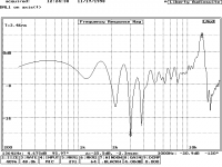
overall trend of the midrange and treble is surprisingly good. (A measured frequency response is attached.)
The prototype loudspeaker is quite inefficient, and a 10W amplifier could not make it go very loud - but as the donor loudspeaker was only rated at ½W, caution might be wise!
NXT say that the DML is almost perfectly omni-directional, and this surprising claim was confirmed, and because of this ideal directivity, DMLs have recently been installed as the surround loudspeakers in the film screening room at Tobis (Portugal). As would be expected, there are no boxy colourations. One of NXT's more surprising claims is that the DML does not suffer appreciably from the inverse square law, and that sound intensity falls only gradually with distance from the loudspeaker. Amazingly, this claim too seems to be true over the close and medium field.
Despite being marketed as a wall mounting loudspeaker, the prototype DML does not take kindly to being placed near a wall, and produces a "cuppy" colouration. Its surface does not like touching any rigid surfaces. The voice coil rocking problem could be solved by a donor loudspeaker having a dual suspension, but these are rare. Traditional Alnico or more modern rare earth magnets are smaller diameter than ferrite magnets, and might reduce rocking.
References:
(1). “Newell refits processing labs with NXT” M Collins. pp 44 Pro Sound News Aug 99
"The white paper", New Transducers Ltd, 1996
M Colloms,"High performance loudspeakers" 5th ed, pp39, 1997
Operating principles:
The DML is an entirely new way of coupling the movement produced by the motor system to air to produce sound. Conventional methods drive a notionally rigid cone from its apex,
or drive a flexible diaphragm at all points - both methods seek to minimise resonance. By contrast, the DML actively encourages as many resonances as possible in the hope that they can be distributed across the audio band sufficiently evenly that a flat response may be obtained.
Essentially, the loudspeaker consists of a large freely suspended flat panel energised at a single point.
A moving coil motor may be used by bonding the coil directly to the panel and allowing the spider to support the mass of the magnet. The coil thus drives the inertia of the magnet, and because for every action, there is an equal and opposite reaction, the coil sets up bending waves within the panel.
Alternatively, a piezo bimorph may be bonded to the panel, thus directly bending the panel to set up the bending waves.
So far, the principle seems simple, but operation is critically dependent on:
Panel proportions
Panel area
Panel material
Motor positioning
The technology has been developed by NXT, who are understandably reticent about details, since they licence the (patented) technology. Nevertheless, it is quite simple to make a prototype to demonstrate the unusual features of the DML...
Construction:
Art shops sell 5mm foam cored card for modelling purposes - a single sheet suffices to make a pair of loudspeakers. If we know little about the physical characteristics of the material, we can only adjust panel proportions and motor positioning.
When the distance from one edge to the opposite edge is an odd number of half-wavelengths, a standing wave will be formed, and there will be a peak in the response. An even number of half-wavelengths causes a null. If the standing waves across the width of the panel can be chosen so as to avoid the set formed along the length, a reasonably flat response should result. Proportions related to prime numbers ought to be fruitful, and
a little computer experimentation suggested proportions of 13/7, so each panel was cut with a scalpel to 77cm x 41.5cm. A motor supporting the magnet purely from the spider is inviting rocking and scraping of the coil, so a moving coil loudspeaker with a light magnet is needed, and a 65.5mm Mylar coned loudspeaker from Maplin (part number; VC86) costing £1.99 was chosen for
modification.
The rubber sealing gasket can be gently pulled away, and the cone cut away from the perimeter of the basket using a scalpel. A pair of nail scissors can then cut the cone from the coil former (except for the areas supporting the lead-out wires from the voice coil). The tails from the voice coil should be de-soldered from the tag strip, and the basket cut away from the magnet using a pair of tin snips. Using the scalpel, cut way most of the metal foil dust cap to reveal the coil former. Using the nail scissors, carefully trim as much of the remaining cone away as possible, ideally leaving only the coil former with very narrow
strips (1mm) of cone supporting the voice coil wires.
Motor positioning was chosen using Golden Mean (1:1.618) proportions, and placed 29.5cm along the length, and 16cm across the width.
The motor is fitted by glueing the voice coil former to the panel with plenty of super-glue. Light, flexible wires can be super-glued to the panel prior to soldering them to the voice coil tails. Finally, firmly super-glue the cone tails to the panel.
Results:
As predicted, if the panel is positioned vertically, the magnet rocks and scrapes on the voice coil, producing distortion. From the point of view of voice coil scraping, the ideal panel position is horizontal, with the motor hanging beneath the panel.
The foam cored card is quite expensive (£11), but the donor loudspeakers were very cheap, so the finished loudspeakers cost only £15 total for the pair, whilst taking one hour to make. Despite this, the sound is subjectively far better than might reasonably be expected!
There is little bass below 150Hz, and overloading the loudspeaker
at low frequencies produces some very odd noises, but the
overall trend of the midrange and treble is surprisingly good. (A measured frequency response is attached.)
The prototype loudspeaker is quite inefficient, and a 10W amplifier could not make it go very loud - but as the donor loudspeaker was only rated at ½W, caution might be wise!
NXT say that the DML is almost perfectly omni-directional, and this surprising claim was confirmed, and because of this ideal directivity, DMLs have recently been installed as the surround loudspeakers in the film screening room at Tobis (Portugal). As would be expected, there are no boxy colourations. One of NXT's more surprising claims is that the DML does not suffer appreciably from the inverse square law, and that sound intensity falls only gradually with distance from the loudspeaker. Amazingly, this claim too seems to be true over the close and medium field.
Despite being marketed as a wall mounting loudspeaker, the prototype DML does not take kindly to being placed near a wall, and produces a "cuppy" colouration. Its surface does not like touching any rigid surfaces. The voice coil rocking problem could be solved by a donor loudspeaker having a dual suspension, but these are rare. Traditional Alnico or more modern rare earth magnets are smaller diameter than ferrite magnets, and might reduce rocking.
References:
(1). “Newell refits processing labs with NXT” M Collins. pp 44 Pro Sound News Aug 99
"The white paper", New Transducers Ltd, 1996
M Colloms,"High performance loudspeakers" 5th ed, pp39, 1997
Attachments
Congrats. Great research!
If you have the facilities, I wonder what a step response would look like.
The only really bad parts of the response are those three notches between 2KHz and 4KHz. Otherwise, you have a decently smooth response.
Looks like you might really be onto something.
If you have the facilities, I wonder what a step response would look like.
The only really bad parts of the response are those three notches between 2KHz and 4KHz. Otherwise, you have a decently smooth response.
Looks like you might really be onto something.
I am also curious if you would be interested in running a two tone test to test modulation distortion in your loudpseaker. Paul Klipsch ran these tests to demonstrate the large amounts of modulation distortion loudpseakers generate if they play too big a slice of the audio spectrum. I have posted both the formula for intermodualtion distortion and the graph made with a tone generator and a spectrum analyzer on the following thread:
http://www.diyaudio.com/forums/showthread.php?threadid=9818&highlight=modulation
The large size of your speaker would tend to indicate low modulation distortion. However, the distributed mode method might have large numbers of resonances, etc., that seem to sum up. If you have the time, and interest, a two tone test might prove illuminating.
Freeware spectrum analyzers are available on the net, if you don't have one.
If you do run the test, you will need to know the excursion necessary to produce the low note in order to plug into Klipsch's formula. I have reprinted Small's chart for Volume Displacement necessary to produce bass tones at chosen SPLs in the following thread. Just divide the appropriate number by the area of your Distributed Mode Speaker, and you are all set.
http://www.diyaudio.com/forums/showthread.php?threadid=5668&highlight=Volume+Displacement+Chart
In my opinion, low modualtion distortion is half the reason electrostatics and planars sound so good. If your speaker has low modulation disortion too, that would be a very strong argument in favor of it's adoption as a high fidelity system.
Anyway, thanks for your initiative and good work so far.
EC8010,
Interesting measurement. looks like you have summing and cancelling of the front and rear waves, but dipole rolloff doesn't begin until later. How close was the panel to walls/ceiling/floor during the measurement?
Perhaps a small frame could be built to both suspend the panel from the front, and the driver magnet from the rear, similar to this:
http://www.linkwitzlab.com/m_panel.htm
This would keep them aligned and hopefully allow vertical placement. It will be interesting to see if the peaks and nulls move south, or if they are a result of summing and cancelling of modes on one side of the panel. I've seen data that other dipole planars and line sources have floating nulls and peaks which change with distance, but this panel is producing in phase and out of phase info from both sides. Question is, How audible is it? Is it averaged out at listening distance?
Maybe you could use a reconing kit to attach the panel to the frame at different points ?
regards,Jason
EC8010 said:The technology has been developed by NXT, who are understandably reticent about details, since they licence the (patented) technology. Nevertheless, it is quite simple to make a prototype to demonstrate the unusual features of the DML...
I went to both the British Patent Office and the American Patent office to see if the patents have any of the aforementioned details.
The British Patent Office, when you go to the search box and write "distributed mode loudspeaker", gives you many patents. The earliest seem to be:
US6031926
US2001017924
http://gb.espacenet.com/
When you go to the American Patent Office Search box and fill in "bending wave" you get quite a few hits, including the two I mentioned previously. To my knowledge, those two are the earliest patents of this idea. Martin Colloms is listed as one of the inventors.
http://www.uspto.gov/patft/index.html
They have a couple of patents where a second panel with different bending resonances is attached to the first. In one patent, the second panel is nondriven, in the other, it is driven by a voice coil. Could those be an attempt to eliminate deep notches such as we see betwee 2KHz and 4KHz in your prototype?
If you do go to the US Patent Office, you might have some trouble downloading the Image Viewer. I had to download IE 6 to get it to work- versions of IE 5 or 5.5 just didn't work with it.
diypole said:How close was the panel to walls/ceiling/floor during the measurement?
Perhaps a small frame could be built to both suspend the panel from the front, and the driver magnet from the rear, similar to this:
The panel was about 1.5m from the nearest boundary.
Yes, a frame can be made, and I have done so. The frame is about 2ft by 3ft, and supports the panel all round the edge in the manner of a trampoline (lots of knicker elastic). The advantage (apart from vertical operation) is that a heavier motor can be used, which improves efficiency (ratio of motor mass to panel mass). However, aligning and fixing the motor so that the coil doesn't scrape is difficult, and I haven't yet succeeded. despite this, the panel is much more sensitive, and produces some bass, but at the expense of HF. It seems that 7 octaves is the limit, and a heavier motor on the same panel simply shifts those octaves down in frequency. Unfortunately, I donated this prototype to my previous employer, but if I have time, I will pop in and take a few photographs, and post them.
I can't currently make loudspeaker measurements as my new computer won't accept my old soundcard.
Re: Re: Distributed mode loudspeakers (DMLs)
Thanks for the references, I shall look them up. My understanding is that the original invention came about as a result of trying to null fighter aircraft cockpit noise with out-of-phase noise. It was found that the loudspeakers produced more noise by exciting the panels on which they were mounted than by vibrating their cones!
kelticwizard said:I went to both the British Patent Office and the American Patent office to see if the patents have any of the aforementioned details.
Thanks for the references, I shall look them up. My understanding is that the original invention came about as a result of trying to null fighter aircraft cockpit noise with out-of-phase noise. It was found that the loudspeakers produced more noise by exciting the panels on which they were mounted than by vibrating their cones!
LOL, when I read your quote of my post, I suddenly realized that I should have said I went to the British Patent Office and the American Patent Office websites about these speakers. A reading of the quotes seems to indicate I went down there in person! ")
This type of speaker has been discussed on this forum before, although nobody has gone as far as you have with them. The following link contains the earlier thread. On the thread is a link to an article on the figher aircraft angle. I think you have it right about how it came about.
Also, Armstrong now makes ceiling panels with this technology. Link also at the earlier thread.
http://www.diyaudio.com/forums/showthread.php?threadid=1647&highlight=NXT

No future developments planned
Although I only presented one set of measurements (they were the only ones I could find), I have actually measured about thirty different shapes and sizes of panels with different exciter positions. I set this as a task for 12 year-olds at Summer School to make these loudspeakers, and let them choose their dimensions and placings after explaining prime numbers and ratios to them. All the loudspeakers were measured, but I don't have the measurements to hand. I think a few were better than my prototype...
Although I only presented one set of measurements (they were the only ones I could find), I have actually measured about thirty different shapes and sizes of panels with different exciter positions. I set this as a task for 12 year-olds at Summer School to make these loudspeakers, and let them choose their dimensions and placings after explaining prime numbers and ratios to them. All the loudspeakers were measured, but I don't have the measurements to hand. I think a few were better than my prototype...
Here are those links for the Armstrong Ceiling Tiles, the other thread's links were dead.
The SoundPanel Pro had much the better response. Note the response curve divisions are plus or minus 20 dB.
http://www.armstrong-ceilings.co.uk/ICSound/Sound.asp
http://www.armstrong-ceilings.co.uk/Ressources/soundsystem/GB/sound_panel_cs100.pdf
http://www.armstrong-ceilings.co.uk/Ressources/soundsystem/GB/sound_panel_pro.pdf
Here is a page with references to current products that use the principle.
http://www.flat-speaker.co.uk/default.asp?loc=viewmodels.asp?sort=1
One thing. I notice that you use rubber to suspend the speaker from the frame. This is somewhat like the surround in a conventional speaker.
My question is: Are you sure this is the way to go? With all the talk of "bending waves", maybe the idea is to hold the edges rigid and not to allow them that relatively easy movement. Maybe by forcing them to flex back and forth, confined by a rigid frame, the diaphragm material itself is forced to flex and beneficial resonances are activated. Flexible suspensions are used on normal speakers where the goal is piston-like movement. The "bending wave" principle is the exact opposite of that.
The speakers don't have a very large excursion anyway, so the diaphragm material should be capable of flexing the tiny amount it needs to, even when rigidly supported at the edges.
Maybe what you need to do is build a wooden frame that encloses the edges like a picture frame, and see what happens.
Just a suggestion.
kelticwizard said:I notice that you use rubber to suspend the speaker from the frame. This is somewhat like the surround in a conventional speaker.
My question is: Are you sure this is the way to go? With all the talk of "bending waves", maybe the idea is to hold the edges rigid and not to allow them that relatively easy movement.
The edges need to be as free to vibrate as possible. Clamping the edges is very nasty. You'd be amazed by how much the edges vibrate on the trampoline version with a bit of bass. Its a good couple of millimetres! The thin knicker elastic only contacts every 50mm, or so, and there is a 50mm gap between the panel and the frame. Backward and forward movement is barely affected, but it is very rigid laterally. Which is what is needed.
Knock one up. After all, if a 12 year-old (both sexes) can do it...
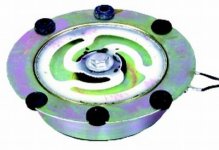
Aura Shaker Motor Assembly
One of these thing from Jaycar might be suitable to drive a panel if you attached it to the bolt in the centre. No more voice coil scraping problems then. It is supposed to be subsonic, but it may have a useable response where you want.
One of these thing from Jaycar might be suitable to drive a panel if you attached it to the bolt in the centre. No more voice coil scraping problems then. It is supposed to be subsonic, but it may have a useable response where you want.
Attachments
I am adding this last comment for two reasons.
First, to let EC8010 know that piezos are also used to drive these things. Piezo elements can be obtained by buying the cheapest Motorola, (now CTS,) horn tweeter available-probably around $10 or it's equivalent-and taking out the element that drives it. Find some way for the frame to press the piezo against the diaphragm, and you no longer have to worry about voice coil rub. This is because there will be no voice coil in the speaker.
The second reason to add this was so that Circlotron won't be the last poster in this thread anymore. He's getting touchy about that lately.
Yamaha YSP1
Hi, I have just been reading an article in a magazine about the Yamaha YSP-1 surround sound speaker. It uses 42 seperate drivers and some cunning electronics to reproduce spatial cues. I haven't had the chance to read the entire article but the concept seems similar to the IOSONO wave field synthesis technique. I am just wondering if a similar system to the YSP-1 could be implemented using DML speakers. I have a 10in/10out soundcard on my pc and I am curious to know if (in theory) i could construct a DML panel like you described and use several drivers to produce a similar system. I do not know very much about DML technology so if anyone has any interesting reading they could recommend I would appreciate it.
Since I do not have the knowledge to produce a dolby compatible system, I was wondering if the drivers could be used as part of an ambisonics array? Any thoughts would be appreciated.
Thank you!
arnold_the_cat
- Status
- This old topic is closed. If you want to reopen this topic, contact a moderator using the "Report Post" button.
- Home
- Loudspeakers
- Multi-Way
- Distributed mode loudspeakers (DMLs)