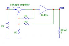
I have made the amplifier with separate voltage amp stage and power buffer. I don`t have measurement tools so I simulated distortion vs global NFB.
Input voltage amplifier has local 6dB feedback loop and it is constant. Only global feedback loop around buffer is changed for different data:
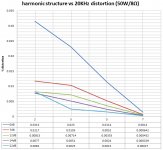
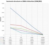
On the graph X axis is 2nd, 3rd, 5th and 7th harmonic. Fundamental is 20KHz.
On the graph Y axis is distortion %.
Separate colors are for 0dB, 7dB, 12dB, 14dB and 22dB of GNFB.
Attachment is block schematic and chart data, it might be interesting to someone")
Input stage is complementary jfet/bjt and the power buffer is a all bjt triple EF.
P.S. Interesting thing is there is no 5th and 7th harmonic rise with raising feedback factor as some are advocating...
Input voltage amplifier has local 6dB feedback loop and it is constant. Only global feedback loop around buffer is changed for different data:
On the graph X axis is 2nd, 3rd, 5th and 7th harmonic. Fundamental is 20KHz.
On the graph Y axis is distortion %.
Separate colors are for 0dB, 7dB, 12dB, 14dB and 22dB of GNFB.
Attachment is block schematic and chart data, it might be interesting to someone
Input stage is complementary jfet/bjt and the power buffer is a all bjt triple EF.
P.S. Interesting thing is there is no 5th and 7th harmonic rise with raising feedback factor as some are advocating...
Attachments
Last edited:
Anyone had a similar experience with real measurements? (I used Cordell`s model and MicroCap for simulating).
Anyway the interesting fact is the sound perception: With 0dB feedback - open loop- I hear the not so precise bass and a little (just little) grain in the high/midrange tones, but with 6dB of feedback and more the bass is tighter (just right) and the hi/midrange is grainless. There is, as I hear it, almost no difference between say 6dB and 22dB of feedback, before I did the simulating measurements in spice I stayed at 14dB of feedback as the optimal point (to my ears). It`s a purple straight line on the graph, maybe it`s just coincidence...
When started to construct this amplifier from a white sheet of paper (monitor) ,I tried to construct it to be as linear as I can so it could run open loop. In the final, it maybe an open loop amplifier, I hope the sound will be better because I`m running it now in mono with two paralleled 4Ohms speakers so it works with the 2 Ohms load and only one pair of the output bipolar transistors for the output in a prototype. BTW output triple is class AB.
Another interesting thing is that there is no dominant 3rd harmonic as in most complementary class AB amps at full power (50W/8Ohm in my case).
Any comments are welcome.
Cheers Borko.
Anyway the interesting fact is the sound perception: With 0dB feedback - open loop- I hear the not so precise bass and a little (just little) grain in the high/midrange tones, but with 6dB of feedback and more the bass is tighter (just right) and the hi/midrange is grainless. There is, as I hear it, almost no difference between say 6dB and 22dB of feedback, before I did the simulating measurements in spice I stayed at 14dB of feedback as the optimal point (to my ears). It`s a purple straight line on the graph, maybe it`s just coincidence...
When started to construct this amplifier from a white sheet of paper (monitor)
,I tried to construct it to be as linear as I can so it could run open loop. In the final, it maybe an open loop amplifier, I hope the sound will be better because I`m running it now in mono with two paralleled 4Ohms speakers so it works with the 2 Ohms load and only one pair of the output bipolar transistors for the output in a prototype. BTW output triple is class AB.Another interesting thing is that there is no dominant 3rd harmonic as in most complementary class AB amps at full power (50W/8Ohm in my case).
Any comments are welcome.
Cheers Borko.
Last edited:
P.S. Interesting thing is there is no 5th and 7th harmonic rise with raising feedback factor as some are advocating...
If your amp is reasonably linear to begin with, you won't see any re-entrant distortion (or very little of it).
The original article that showed it was on a single FET stage, which is nonlinear as hell.
Jan
If your amp is reasonably linear to begin with, you won't see any re-entrant distortion (or very little of it).
The original article that showed it was on a single FET stage, which is nonlinear as hell.
Jan
I know the article I just wanted to check it...
It is linear to my best efforts.
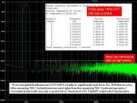
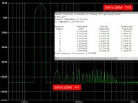
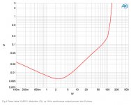
This is the harmonic distribution at 1W/8 Ohms with 20KHz fundamental
Attachments
Last edited:
---ONE SCHOOL OF AMPLIFIER DESIGN---
"If you use global feedback use A LOT of it!
It is better to significantly beat down ALL THD than to worry if the remaining TINY 3rd/odd harmonics are higher than the remaining TINY 2nd/even harmonics.“
Some early Japanese power amps followed this philosophy and had poor subjective reviews. Perhaps the shape of the clipping waveform and clipping recovery artifacts are also important to study. Perhaps the distortion profile when the speaker load dramatically changes: like resistance drop; like inductance increase; like LRC resonances in the crossover; like dampening factor; etc... are also important to study.
Attachments
Would be nice if you put in a dB scale on Y axis, avoids having to manually calculate the 2nd at -100 dB. I think.
Jan
I thought it is easier to understand like this, the 2nd on the 1W/8 Ohms graph is about 0.0015%.
---ONE SCHOOL OF AMPLIFIER DESIGN---
"If you use global feedback use A LOT of it!
It is better to significantly beat down ALL THD than to worry if the remaining TINY 3rd/odd harmonics are higher than the remaining TINY 2nd/even harmonics.“
Some early Japanese power amps followed this philosophy and had poor subjective reviews. Perhaps the shape of the clipping waveform and clipping recovery artifacts are also important to study. Perhaps the distortion profile when the speaker load dramatically changes: like resistance drop; like inductance increase; like LRC resonances in the crossover; like dampening factor; etc... are also important to study.
As confirmed in simulation, with higher feedback, 2nd and 3rd harmonics are getting close to a 5th and 7th level, even lower then 5th and 7th and I think that don`t sounds right, even if they are very low (at least to my ears).
From my listening experience the Hiraga`s harmonic pattern theory is right on the spot.
Also a very important thing is flat frequency vs distortion characteristics of the amp, at least to 20KHz. (most amps have rise in distortion from about 1KHz to higher frequencies).
So my conclusion is a modest feedback and Hiraga`s harmonic pattern with progressively decreasing harmonic amplitudes.
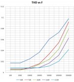
THD vs F graph is next...
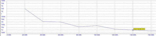
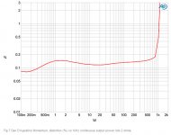
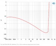
THD vs F graph (100Hz - 200KHz) and corrected vrsion of the first graph :
As you can see open loop amp (0dB feedback line) on the right graph is a ideal case of Hiraga`s philosophy but on the left graph highest (in fact modest) feedback line for 22dB feedback is the most ideal - a straight line from 100Hz to 20KHz. What is right?
As you can see open loop amp (0dB feedback line) on the right graph is a ideal case of Hiraga`s philosophy but on the left graph highest (in fact modest) feedback line for 22dB feedback is the most ideal - a straight line from 100Hz to 20KHz. What is right?
Attachments
Last edited:
I thought it is easier to understand like this, the 2nd on the 1W/8 Ohms graph is about 0.0015%.
Well I'd settle also for a % scale; both dB and % are used in audio. The graph I mentioned had V and mV, which is unusual, takes an effort to convert to either dB or % and invites errors. I mean, whoever puts up the graph WANTS us to get it right, right?
BTW There's a reason why generally Y-scales are either in dB or in % but then log. It's because the way we experience it is also roughly logarithmic scaled so a dB or log % scale corresponds better to our perception.
Jan
Last edited:
As confirmed in simulation, with higher feedback, 2nd and 3rd harmonics are getting close to a 5th and 7th level, even lower then 5th and 7th and I think that don`t sounds right, even if they are very low (at least to my ears).
From my listening experience the Hiraga`s harmonic pattern theory is right on the spot.
Also a very important thing is flat frequency vs distortion characteristics of the amp, at least to 20KHz. (most amps have rise in distortion from about 1KHz to higher frequencies).
So my conclusion is a modest feedback and Hiraga`s harmonic pattern with progressively decreasing harmonic amplitudes.
THD vs F graph is next...
The thing is, that the harmonic structure changes with feedback depend a lot on the linearity of the amp before you apply feedback.
I agree that a nice decreasing spectrum probably is best, but with some amps that results from moderate feedback, while others need much more.
So there is no direct link between how much feedback is used and the thd spectrum decay.
Jan
So I`ve made a very linear amp
Well I'd settle also for a % scale; both dB and % are used in audio. The graph I mentioned had V and mV, which is unusual, takes an effort to convert to either dB or % and invites errors. I mean, whoever puts up the graph WANTS us to get it right, right?
BTW There's a reason why generally Y-scales are either in dB or in % but then log. It's because the way we experience it is also roughly logarithmic scaled so a dB or log % scale corresponds better to our perception.
Jan
I did the graph in Excel, quickly just to show the point...
Jan what do you think of other two things I mentioned:
1. THD vs F - a flat line at least to 20KHz.
2. THD vs Power linear increase of thd with power increasing.
Anyone else did such simulation/listening experiments??
depends on the open loop gain, more profit margin, less distortion
Vliv rezervy zisku na zkreslení

http://www.federmann.cz/index.php/n...-fi-zesilovae-a-milniky-jejich-topologii.html
Vliv rezervy zisku na zkreslení
http://www.federmann.cz/index.php/n...-fi-zesilovae-a-milniky-jejich-topologii.html
Last edited:
I did the graph in Excel, quickly just to show the point...
Jan what do you think of other two things I mentioned:
1. THD vs F - a flat line at least to 20KHz.
2. THD vs Power linear increase of thd with power increasing.
Anyone else did such simulation/listening experiments??
Flat THD vs F would be nice, but some people get that by increasing the THD at low frequency - that's not good of course.
I believe if you have two amps with same THD at say 10kHz, but one has lower at 1kHz, that one is better even when the THD vs F is not flat.
For the THD vs P it should stay flat until it runs out of steam, then do a soft clip.
Jan
200 dB feedback isn't "better" with what we know about audio, human hearing and amplifier noise, even much over 120 dB is already swamped by the noise floor of most amps
a eventual limitation of feedback loop gain is sensor, gain block noise - you look to be in the pointless high gain region where amplified electronic parts noise is the major signal in your early feedback gain stages
ordinarily the issue isn't discussed in electronic feedback amps since we have usually have great S/N and most engineers stop far short in applying loop gain
some instrumentation can benefit from loop gain >10e6 down to sub Hz, in audio we don't have any evidence human hearing integrates long enough for performance exceeding decent electronic's noise floor in even 10 Hz BW could ever be perceived
I am quite happy seeing 100-120 dB loop gain in my sims – even better if that can hold up to 20 kHz – but I really don't think 180+ dB would ever be “better” and would usually come with severe costs
Last edited:
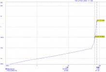
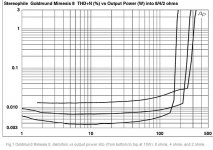
Some graphs from popular amplifiers for reference- Stereophile measurements. All amps are classAB :
BTW I guess most of members who are interested in amplifier design know some details of construction of amps mentioned...
So, any conclusions?
BTW I guess most of members who are interested in amplifier design know some details of construction of amps mentioned...
So, any conclusions?
Attachments
- Home
- Amplifiers
- Solid State
- Distortion vs Global-Feedback (simulated)