Scott,
I noticed a problem when trying to extract the parameters of the MJL3281a from the characteristic curves of the data sheet. Estimating the Early Voltage from the slope of the characteristic curves gave one number that was relatively low, while estimating it from the beta vs. Ic and Vce (for which beta varied only a small amount) gave a much higher number. The beta curves were taken at lower voltages and currents than those on the characteristic curves. So it appears that the devices don't fit the Gummel-Poon model of Early Voltage behavior particularly well.
In RF and microwave circles, the MEXTRAM model is becoming more popular now http://www.semiconductors.philips.com/Philips_Models/bipolar/mextram/.
I noticed it models a bias-dependent Early effect. Have you ever used MEXTRAM, and if so, does it give more accurate distortion predictions than Gummel-Poon? I suppose this question might be more than you're willing to disclose, so I won't feel bad if you ignore it") .
.
I noticed a problem when trying to extract the parameters of the MJL3281a from the characteristic curves of the data sheet. Estimating the Early Voltage from the slope of the characteristic curves gave one number that was relatively low, while estimating it from the beta vs. Ic and Vce (for which beta varied only a small amount) gave a much higher number. The beta curves were taken at lower voltages and currents than those on the characteristic curves. So it appears that the devices don't fit the Gummel-Poon model of Early Voltage behavior particularly well.
In RF and microwave circles, the MEXTRAM model is becoming more popular now http://www.semiconductors.philips.com/Philips_Models/bipolar/mextram/.
I noticed it models a bias-dependent Early effect. Have you ever used MEXTRAM, and if so, does it give more accurate distortion predictions than Gummel-Poon? I suppose this question might be more than you're willing to disclose, so I won't feel bad if you ignore it
.real
hi wimms
a real measurement of this kind:
http://babelfish.altavista.com/babe...001.nm.ru/Voltage_measurement/measurement.htm
(babelfish translation!
an example of fine accurate nonlinearity measurement for simple circuit
hi wimms
a real measurement of this kind:
http://babelfish.altavista.com/babe...001.nm.ru/Voltage_measurement/measurement.htm
(babelfish translation
!an example of fine accurate nonlinearity measurement for simple circuit
andy_c said:Scott,
I noticed a problem when trying to extract the parameters of the MJL3281a from the characteristic curves of the data sheet. Estimating the Early Voltage from the slope of the characteristic curves gave one number that was relatively low, while estimating it from the beta vs. Ic and Vce (for which beta varied only a small amount) gave a much higher number. The beta curves were taken at lower voltages and currents than those on the characteristic curves. So it appears that the devices don't fit the Gummel-Poon model of Early Voltage behavior particularly well.
In RF and microwave circles, the MEXTRAM model is becoming more popular now http://www.semiconductors.philips.com/Philips_Models/bipolar/mextram/.
I noticed it models a bias-dependent Early effect. Have you ever used MEXTRAM, and if so, does it give more accurate distortion predictions than Gummel-Poon? I suppose this question might be more than you're willing to disclose, so I won't feel bad if you ignore it
We use our own extended Gummel-Poon model for Bi-polars. A simply linear model of the Early effect will generally not give you much distortion. I would say these days simulators start falling apart at the 70-80dB level. One must be careful when discussing distortion from subtle device related effects or when it is inherent in the circuit topolgy and bias levels.
scott wurcer said:
We use our own extended Gummel-Poon model for Bi-polars. A simply linear model of the Early effect will generally not give you much distortion. I would say these days simulators start falling apart at the 70-80dB level. One must be careful when discussing distortion from subtle device related effects or when it is inherent in the circuit topolgy and bias levels.
Yes, so true. I get 0 feedback (global/interstage) circuits of
various function to go well below 0.001%.
IME the linearity is foremost based on your 2nd point,
topology and bias levels; however it is impossible to go
further than a certain point without addressing the first
point; subtle device related effects.
T
Hi Wimms,
Thank you for showing your outline circuit.
Due to other committments it has taken me some time to get my mind around your investigations.
I note that the reference virtual amp does not include output C or L, which both change with amplitude, frequency and load in a real propagation delayed NFB amplifier due to load current variation affecting gain bandwidth product throughout each waveform cycle.
If the input trace is V(out)*4u, then this itself is asymmetrical, and therefore time shifted errors will not have a smooth symmetrical basis upon which to base conclusions.
Note how I(Rout) does not cease immediately. Whether this error arises at the start or finish of a toneburst is irrelevent, it is a propagation delay/ NFB loop/ loudspeaker impedance artifact, here having independent tweeter energising (waveform distorting) capability, as illustrated by V(out-inp) and V(ref-res).
It would be interesting to see V(ref-out) with the virtual amp having internal C and L, in Farads and micro-ohms, for this should properly isolate propagation delay/ NFB loop induced error for the circuit under test.
Also, although you are concerned about sudden start-up, the error trace due to continuation after a sudden start-up via a good amplifier is unlikely to be much different to your own delayed modulation trace after the same 10uS, with the benefit that any introduced errors may be viewed against a symmetrically energising sinewave input.
Re your impression that the NFB 'needs to compensate before the input arrives'.
This is of course is impossible. A series output inductor can help the amplifier here, but it also increases amplifier-loudspeaker interface distortion because it is outside the NFB loop and driven by extremely low impedance.
Quad very cleverly use a series output inductor as part of the NFB output sensing current dumping bridge, but I found this less good sounding than simple class-A.
I'm all ears to hear any suggestions that voltage source drive is not best, but I believe the main differences causing amplifier 'sound' relate to series output impedance, as opposed to output resistance, and maybe a standardised 220mR, as used by JLH so long ago would prove useful.
Re my JLH/class-AABB. The splitter currents are imbalanced and become increasingly so due to NFB with approaching load or input induced overload. That is why I eventually, but reluctantly, gave up on it.
It is not the bootstrap that becomes exhausted, but that the lower device receives additional imbalancing currents through the driver transistor from the base of the upper device, plus, driver base current passing straight through to the lower output from the input stage. This is all simulatable, as well as audible!
Pulldown resistors can be seen as being necessary during high frequency audio output to minimise base carrier/charge build up so that an output device quickly drops out of high load current conduction as its V.ce is suddenly increased by a push-pull partner. This applies more to non-complementary output stages than to centrally biased NPN/PNP output stages.
Hi Nelson.
I quite agree.
We can only gain knowledge of the mechanisms involved, not read the simulations as if factual.
Cheers ........... Graham Maynard.
Hi Graham,
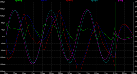
But for completeness I include run of same amp with sudden starting sine. It is indeed pretty similar. The main difference is output current that in sudden sine case wobbles for considerable time on time axis like spring that has been hit instead of compressed.
Re voltage drive, it really starts here - cone motion force is proportional to *current* through it, voltage on crossover input is pretty far from controlling linearity of that one.
I'm not sure I follow you. In what way could I have added output C and L to the virtual amp? Please advise how to do that meaningfully. The DUT amp had only 1 compensation (splitter) cap in it, no L. Still, imo the exercise was to graph the difference between ideal and real amp. The difference between DUT into Rload and DUT into speaker load you already illustrated.Graham Maynard said:I note that the reference virtual amp does not include output C or L, which both change with amplitude, frequency and load in a real propagation delayed NFB amplifier due to load current variation affecting gain bandwidth product throughout each waveform cycle.
..
It would be interesting to see V(ref-out) with the virtual amp having internal C and L, in Farads and micro-ohms, for this should properly isolate propagation delay/ NFB loop induced error for the circuit under test.
My goal was to reduce harmonic pollution to minimum, to avoid (still excessive) impact of phase response to different frequencies. I don't think asymmetry is much of trouble here.If the input trace is V(out)*4u, then this itself is asymmetrical, and therefore time shifted errors will not have a smooth symmetrical basis upon which to base conclusions.
Sudden startup created spikes, oscillation at both ends, and unknown time shifts that I can't make sense of. Later pure sinewave shows no transient details. I picked the waveform that has severe yet harmonic transient that both amp and speaker are still expected to follow. Imo this rids us from worries that we have overdriven the system with signal to which the system can only answer with spurious response.Also, although you are concerned about sudden start-up, the error trace due to continuation after a sudden start-up via a good amplifier is unlikely to be much different to your own delayed modulation trace after the same 10uS, with the benefit that any introduced errors may be viewed against a symmetrically energising sinewave input.
But for completeness I include run of same amp with sudden starting sine. It is indeed pretty similar. The main difference is output current that in sudden sine case wobbles for considerable time on time axis like spring that has been hit instead of compressed.
Do you agree that my impression is valid? Because I'm not 100% confident myself. Though I can see that current-drive amps and non-NFB amps are free from that issue, as neither is stuck on tracking speaker terminal voltage.Re your impression that the NFB 'needs to compensate before the input arrives'.
This is of course is impossible. A series output inductor can help the amplifier here, but it also increases amplifier-loudspeaker interface distortion because it is outside the NFB loop and driven by extremely low impedance.
This is the main point of wondering what is the right method of speaker driving. This non-ceasing of current is present with voltage drive. With current drive, its the voltage that does not cease.Note how I(Rout) does not cease immediately. Whether this error arises at the start or finish of a toneburst is irrelevent, it is a propagation delay/ NFB loop/ loudspeaker impedance artifact, here having independent tweeter energising (waveform distorting) capability, as illustrated by V(out-inp) and V(ref-res).
The crux of the matter is: which is more harming - shorting the stored speaker energy, creating delayed currents in it, or letting it float. In current drive, the current ceases with input signal, but due to high output impedance, terminal voltage is doing dances. Which is worse?I'm all ears to hear any suggestions that voltage source drive is not best, but I believe the main differences causing amplifier 'sound' relate to series output impedance, as opposed to output resistance, and maybe a standardised 220mR, as used by JLH so long ago would prove useful.
Re voltage drive, it really starts here - cone motion force is proportional to *current* through it, voltage on crossover input is pretty far from controlling linearity of that one.
I need some help here. I still don't see how pulldown resistor can help when splitter is driving BJT that never exits class-A, isn't floating but tied to PS, and base current can't reverse until it or splitter drops out of class-A. Can you help me with this? I see this only required in class-AB to minimize crossconductance. In your class-AABB setup, there is in addition fact that high-current B and AB devices have their base pulldowns.Pulldown resistors can be seen as being necessary during high frequency audio output to minimise base carrier/charge build up so that an output device quickly drops out of high load current conduction as its V.ce is suddenly increased by a push-pull partner. This applies more to non-complementary output stages than to centrally biased NPN/PNP output stages.
Attachments
I don't know if this is all familiar, but I'll repost here verbatim what Thomas Dunker wrote on the JoeList. This was also posted here http://www.diyaudio.com/forums/showthread.php?s=&threadid=6224&perpage=10&pagenumber=6 Hopefully this doesn't come as boring.I'm all ears to hear any suggestions that voltage source drive is not best, but I believe the main differences causing amplifier 'sound' relate to series output impedance, as opposed to output resistance, and maybe a standardised 220mR, as used by JLH so long ago would prove useful.
---------------------------------------------------------
Fri, 20 Sep 2002
Subject: [JN] Field-Coils and missing considerations
My assorted ramblings follow:
If you had read up on the issue of flux modulation and resulting harmonic and IM distortion in electrodynamic speaker units, perhaps you'd realize that the only magnet structures likely to rival field coils in that regard would be neodymium ones. Next would be alnico, and finally, the most inferior of the lot, ferrite types. It's all in the BH curves.
The extreme opposite of an old, high efficiency field coil driver, would be a modern, low efficiency ferrite PM driver. It has been assumed that one could make up for a lousy magnet system by calling for greater flux variations from the voice coil, which only increases flux modulation. If you have "something" with a so-so linearity to begin with, and feedback is impractical, the only way to keep distortion down is to make the signal component use as small as possible a fraction of that nonlinear characteristic.
This applies everywhere in an analog audio reproduction chain, speakers being but one example.
Modern speakers have evolved AWAY from literally ALL the wise and scientifically sound rules of thumb that the speaker pioneers of the 1920s-1930s adhered to.
Why does one often find that one is wasting one's time trying to explain that certain "obsolete" technologies may in fact have technological advantages over the contemporary "state of the art"? The main reason that field coils went out of fashion was that permanent magnets eventually became ECONOMICALLY more viable than field coils and because they're not as LABOR-INTENSIVE as coils, and finally that PMs are more CONVENIENT in that they don't require a steady supply of DC. Concerns such as these, having less to do with objective performance, and more to do with profit margins, also pushed horn speakers, triodes, (and eventually pentodes), hardwired circuitry, vinyl, analog tape and various other advanced technologies off the consumer audio scene.
Since the ridiculously shallow "tube vs transistor" discussion sort of came up again ("hey, I once/never heard a good transistor amp"), I can't help but comment on that as well.
If one puts ANY amplifier inside a feedback loop designed to make the amp a "perfect" voltage amplifier - one ALWAYS measures voltage distortion - you have made an amplifier ideally suited to drive a theoretical speaker that basically does not exist - a speaker which has all the same electrical properties as a noninductive power resistor. If we could enjoy music directly from resistive dummy loads, these amps would be all we could ever ask for. Or if we could make a truly voltage controlled SPEAKER with no complex impedance components...
The minimum distortion possible from ANY electrodynamic speaker is a matter of how much distortion there is on the CURRENT driving it, not the voltage, as the industry appears to believe. Rather, if you have the feedback trying to - and more or less succeeding at - maintaining undistorted output voltage while driving a speaker that is very far from a purely resistive load, the feedback not only FAILS TO REDUCE current distortion (it was never asked to) but in fact INCREASES it.
This, however, is no point to make to discredit the IDEA of feedback. Instead we need to look at why, where and how it's being used. For a number of reasons, any form of feedback works better with predictable, stable loads. Should we still want to use feedback in power amps driving speakers, it would seem a lot more sensible to use it to maintain a linear relationship between the INPUT VOLTAGE SIGNAL and the OUTPUT CURRENT SIGNAL.
But since modern speakers are every bit as stupid as modern amps, we'd have to redesign both. Modern speakers depend on low output impedance from the amp for bass damping, and the drivers and crossovers are optimised to work "optimally" in the "undistorted voltage" situation. Here the logic is getting so absurdly twisted that it's "understandable" how the industry pretends nothing is wrong.
I haven't looked into digital amps a great deal. Maybe they avoid some of the problems with conventional amps, but they're still asked to produce "undistorted voltage amplification" - to suit conventional speakers with inadequate self-damping. And speakers still aren't resistive loads, so there can be no proportionality between voltage and current, hence the digital amps don't solve the main problem: There is NO WILL within the industry to radically redesign the whole amp-speaker system , as the known problems seem either unknown or ignored, so we'll be stuck with all the same old market-optimized set of compromises.
The point to make is: An amp that is driving a speaker is part of a system made up of the amp and the speaker, with all sorts of interdependencies, interactions and general MESS. If the speaker is left out of the discussion or analysis of amplifier technology, we can't expect to learn anything useful about the amps. Audiophiles have been puzzled at the uselessness of commonly made measurements on amps and the way some amps are more sensitive to the choice of speakers than others etc. etc.
Seeing no obvious explanations for these discrepancies (which are easily explained), the reaction was to dismiss all attempts at objectively assessing the quality of audio reproduction. It quickly became very unhip to get too scientific about audio. The mantra was "trust only your ears".
Triodes, pentodes, BJTs, FETs etc. are ALL devices which allow us to control a current, and should all be interesting for amplification once we decide to focus on the distortion of a power amp's output CURRENT rather than the voltage.
An SE triode is an obvious example of a sensible amplifier to use with the speakers they made in the 1930s. A stage or two of pure voltage amplification, to the grid of the output triode, producing a corresponding current swing in the transformer primary, and producing a proportional output current on the secondary. If the tubes are all really linear and the speaker can get away with a few hundred milliwatts of power, this is as simple and direct as amplification gets. Given that they didn't rely as heavily on feedback back then, they developed the most linear amplification devices they could manage. Some of the most linear triodes, like 211, RE604 and AD1 are still some of the most linear amplifiying devices EVER made. This was before the idea caught hold that everything can be corrected after the fact, which we're still stuck with.
If speakers hadn't "evolved" the way they did, amplifier technology wouldn't have "evolved" the way it has either.
If an amp today has to have 48 transistors, several feedback loops, a kilowatt's worth of power supply and 50 pounds of heat sinks just to produce the 300 watts required to drive the 0.1% efficient speaker to decent SPLs but still no convincing dynamics, and it still doesn't deal with any of the major known distortion problems, how can anyone talk about progress?
One of my sources for inspiration in audio has been Ragnar Lian, co-founder of Scan-Speak back in the 70s and a living loudspeaker legend here in Scandinavia. He wrote dozens of articles with an inclination similar to mine, explaining known problems and suggesting solutions, and pointing to the decline of audio technology during the second half of the 20th century.
I'm under the impression that he eventually felt that the only people who listened to him were people OUTSIDE the industry, and that within the confines of commercial audio (yes, even "high-end") there is only so much you CAN do because the LAST thing any conservative institution will do is to admit to its past mistakes. Ragnar's vision was to start over from scratch and build integrated amp/speaker SYSTEMS addressing all the problems that the industry has failed to solve since the fateful split between amp manufacturers and speaker manufacturers.
He grew tired of the stubbornness and conservativity of the Scandinavian speaker industry, I guess. If he hasn't retired yet, he's still working as a magnetics engineer on heavy industrial magnetic systems.
Most ironic of all is that now, two decades after CD came out on the market, and with emerging new media that are theoretically capable of insane dynamic range far beyond that of CD, we're STILL struggling to build systems that can competently deal with the best dynamic range available from the old analog media.
Aw, time to step down from the soap box.
Thomas
---------------------------------------------------------
Another interesting post by Thomas is
Theory of the Amplifier / Speaker Interface
http://melhuish.org/audio/article5.html
scott wurcer said:We use our own extended Gummel-Poon model for Bi-polars. A simply linear model of the Early effect will generally not give you much distortion. I would say these days simulators start falling apart at the 70-80dB level. One must be careful when discussing distortion from subtle device related effects or when it is inherent in the circuit topolgy and bias levels.
Hi Scott,
The reason I mentioned the Early effect is a previous discussion about the JLH amp and some simulations that were done of its output stage. The thread is here. The JLH output stage is very sensitive to beta, such that the sharing of current between the upper and lower output devices ends up being quite a strong function of the Early voltage. If the Early voltage of the output device model is made very large, the current sharing is almost perfect between the upper and lower output devices. If the Early voltage is made smaller, the current sharing becomes quite asymmetrical, as the sim in jcx's first post in that thread indicates. This makes the simulated output power somewhat less than it should be. In trying to figure out which of the computed Early voltages to use (based on beta vs Ic with Vce as parameter, or from the slope of the output characteristic curves), it became clear that a bias-dependent Early voltage would be required to really model what's going on.
In the majority of cases I agree that the effect won't be terribly pronounced. But in that thread, it became clear that the JLH design is exceptionally sensitive to beta variations of the output devices.
Anyway, that's the history behind my earlier comments and question.
Andy
Hi Thomas,
I guess we try to satisfy our own requirements rather than trust the commercial designs from those who don't 'start afresh' because they would not profit from doing so.
In my class-AABB there are output 'pulldowns', but there is also a fixed minimum bias from the previous stage which is maintained until very high power demand. Also the drivers do not turn off, and these maintain continuous low level output load contribution.
___________________________
I saw you had given your ideal amplifier an 'output resistance'.
This is part way between an ideal amplifier, and an ideal amplifier plus output impedance that matches the amplifier under test.
An ideal amplifier with passive output impedance is not the same as fundamental nulling because loudspeaker system induced back-emf can generate a fractional voltage across that output resistance.
An ideal amplifier with series output R+L+C that matches the nominal R+L+C values of the amplifier under test will develop the same nominal fractional loudspeaker induced voltage, such that any difference between their outputs will be due to propagation delay/NFB variation in the amplifier under test alone.
Your test arrangement could do this if you add series L+C to the 'output resistance' component already shown connected to your ideal amplier output. I though this was your aim.
To obtain approximate values, run a voltage amplitude plus phase plot for your DUT with the loudspeaker load alone; say 1Hz to 100KhZ Then simulate with (m)R+(u)L+C(F) components in place of DUT and adjust their values until the plots match.
___________________________
It does not matter whether we go for pure voltage or pure current drive, neither alone sounds right via loudspeakers that have reactive characteristics within the AF range.
For quality reproduction should we go for low distortion voltage drive and add a series resistor to minimise increased power draw through dynamically induced impedance dips, followed by a parallel load resistor to minimise instability due to a dynamically induced impedance rise; say 0.22 and 10 ohms, for 8 ohm nominal ?
In the past I have noted that some class-AB ampliers sounded better with a small series resistor or a parallel output resistor. Both options increased the thd at the loudspeaker terminal, and the latter became hot as it increased amplifier loading, yet the audio WAS better.
Maybe there would be merit in trying such components on non-class-A NFB amplifiers, for neither option has been worthwhile on a JLH based class-A.
Cheers .......... Graham.
Nelson Pass wrote:
It ocurrs to me that whether they will or not, one doesn't really know until an equivalent measurement is made on a real life unit. Based on the scale and resolution appearing on the some of the graphs posted achieving that would a heroic act deserving three cheers and drinks on the house.
I'm going to suggest that simulations will not accurately
predict distortion level at -100 db levels. I would not
even trust them at 1% (-40 dB).
It ocurrs to me that whether they will or not, one doesn't really know until an equivalent measurement is made on a real life unit. Based on the scale and resolution appearing on the some of the graphs posted achieving that would a heroic act deserving three cheers and drinks on the house.
Hi Graham,
Do not confuse me with Thomas Dunker, I only reposted one of his old postings. He himself isn't afaik visiting this forum.
Even though finite Zout changes waveforms due to backemf, it must be of same kind as with realistic amp if latter was strictly linear and had static output impedance. Comparing VS+Zout with DUT imo cancels out expected and unavoidable effects of reactive load, and exposes best what nonlinearities DUT leaves, at merely better zoom factor. Thats why DUT isn't really expected to produce null output after fundamental nulling, but similar waveform as VS+Zout is showing. Thats why I tried simulating such waveform, to compare the actual output of DUT to it.
But I'll try your suggestion sometime to see if it makes a difference. I'm just worried that I'll loose solid ground of reference due to handpicking.
Imo we really need to look into effects of perfect voltage drive to the sound, without the freedom to ignore the physics of the transducers. And the physics indeed hints that we should be more concerned about linearity of *current* through transducers, not so much about linearity of voltage on amp terminals.
I find it much more meaningful to attribute audible differences between tubes or SS-no-NFB and SS NFB to that of output drive mode rather than any of the THD. Higher output impedance seems to suit better many, especially efficient drivers. There are physical reasons why that reduces IMD and compression.
http://www.firstwatt.com/current_source_amps_1.htm Nelson certainly can say a word or two on that matter.
http://sound.westhost.com/project56.htm - there is a nice example how to play with controlled output impedance of the amp without wasting too much power on series resistors.
Re sticking with voltage drive.
I believe that reactance of load must be isolated from NFB loop. Quite likely simple series resistance achieves that to a degree, but imo isn't a complete solution. Or NFB must be extremely fast, on the order of (sub)nanosec lag. Current-fedback amps like JLH are approaching that, and perhaps that is the reason why they don't benefit as much from small series resistence. Yet we still need to look into currents in transducers and corresponding acoustic output. I've tried to find a good speakerload model that could reasonably simulate acoustic output, but haven't found one. It would be nice to observe acoustic effects of different approaches.
Does anybody have any good model of speaker that reasonably simulates expected acoustic output, or could help developing one?
Do not confuse me with Thomas Dunker, I only reposted one of his old postings. He himself isn't afaik visiting this forum.
Hmm, let me explain that decision. Perfect voltage source, as in zero output impedance, is clearly impossible physically and thus imo unreasonable goal or reference. We can't get rid of wire resistence. It makes no sense to simulate speakerload attached to perfect voltage source. In ideal Amp with finite output impedance we try to achieve linearity. Simulating with perfect voltage source and finite Zout I'm trying to simulate that. If I add C+L, then I can't help but think of simulating distortion of the amp under test, but my goal was to expose that distortion, nonlinear or reactive.Graham Maynard said:I saw you had given your ideal amplifier an 'output resistance'.
This is part way between an ideal amplifier, and an ideal amplifier plus output impedance that matches the amplifier under test.
An ideal amplifier with passive output impedance is not the same as fundamental nulling because loudspeaker system induced back-emf can generate a fractional voltage across that output resistance.
Even though finite Zout changes waveforms due to backemf, it must be of same kind as with realistic amp if latter was strictly linear and had static output impedance. Comparing VS+Zout with DUT imo cancels out expected and unavoidable effects of reactive load, and exposes best what nonlinearities DUT leaves, at merely better zoom factor. Thats why DUT isn't really expected to produce null output after fundamental nulling, but similar waveform as VS+Zout is showing. Thats why I tried simulating such waveform, to compare the actual output of DUT to it.
But I'll try your suggestion sometime to see if it makes a difference. I'm just worried that I'll loose solid ground of reference due to handpicking.
I hope you gave the post of Thomas a good thought and also checked the link I gave. What Thomas said gathers together alot of background. Dynamic speaker driver is fundamentally current-driven device. He's not alone in touting this. It is true though that neither is best, pure current vs pure voltage drive. Speaker and amp fundamentally needs to be matched to each other. When one realises that, it becomes clear that building ideal amp that would fit any kind of standalone speaker with passive XO is futile - after we build an ideal voltage amp, we hit the issues that perfect voltage isn't ideal signal to drive the passive speakers.It does not matter whether we go for pure voltage or pure current drive, neither alone sounds right via loudspeakers that have reactive characteristics within the AF range.
For quality reproduction should we go for low distortion voltage drive and add a series resistor to minimise increased power draw through dynamically induced impedance dips, followed by a parallel load resistor to minimise instability due to a dynamically induced impedance rise; say 0.22 and 10 ohms, for 8 ohm nominal?
Imo we really need to look into effects of perfect voltage drive to the sound, without the freedom to ignore the physics of the transducers. And the physics indeed hints that we should be more concerned about linearity of *current* through transducers, not so much about linearity of voltage on amp terminals.
I find it much more meaningful to attribute audible differences between tubes or SS-no-NFB and SS NFB to that of output drive mode rather than any of the THD. Higher output impedance seems to suit better many, especially efficient drivers. There are physical reasons why that reduces IMD and compression.
http://www.firstwatt.com/current_source_amps_1.htm Nelson certainly can say a word or two on that matter.
http://sound.westhost.com/project56.htm - there is a nice example how to play with controlled output impedance of the amp without wasting too much power on series resistors.
Re sticking with voltage drive.
I believe that reactance of load must be isolated from NFB loop. Quite likely simple series resistance achieves that to a degree, but imo isn't a complete solution. Or NFB must be extremely fast, on the order of (sub)nanosec lag. Current-fedback amps like JLH are approaching that, and perhaps that is the reason why they don't benefit as much from small series resistence. Yet we still need to look into currents in transducers and corresponding acoustic output. I've tried to find a good speakerload model that could reasonably simulate acoustic output, but haven't found one. It would be nice to observe acoustic effects of different approaches.
Does anybody have any good model of speaker that reasonably simulates expected acoustic output, or could help developing one?
Instrumentation Amplifier
"This method takes advantage of the characteristics of a low-distortion instrumentation amplifier."
from
http://www.elecdesign.com/Articles/Index.cfm?AD=1&ArticleID=8188
"The delay causes the biggest error in the fundamental, which is not important. The harmonics exhibit error also, but as they are so far down in amplitude (with respect to the fundamental), the errors are second order and have little effect on the total distortion calculation."
I seem to recall that Hafler used to suggest that the ouput of an amplifier channel be inverted and summed with the original signal and fed into the second channel. The result in the second channel is the non linearities. You listen to the second channel and get a relative idea of amplifier quality.
Hi Wimms,
Please forgive my occasional confusions, these are due to time shortages and cerebral stress from unresolved head injury, also the nature of this inkless forum. I am okay sitting at a table with paper and written replies. Went through another bad patch recently, so am only now catching up since my last reply.
Thanks for the links - good to see their content published.
Of course all of this was previously realised here, but there has still not been any expression of possibility for back emf induced amplifier non-linearity due to amplifier NFB loop/propagation delay.
Unfortunately you modelled my 'relatively linear' AABB circuit, whereas I feel that either your 'Distortion Microscope' development or my 'X-Y' monitor would show up significant error products when other more conventional amplifier circuits are virtual loudspeaker loaded.
These 'interface' distortions have nothing to do with the unavoidable voltage/current loudspeaker drive arguments that tend to be simple in nature, but are much more complex and can be orders of magnitude greater than thd figures suggest in non-class-A designs. They also remain largely unrecognised - unaccepted - undiscussed.
This was why I suggested your reference amplifier could have output L and C as well as R, so that back emf induced loudspeaker error would not mask amplifier induced error. Your last test circuit could be better than mine at imaging interface induced distortion in isolation. Try it with another circuit, not one where I have attempted to already minimise the errors you are looking for.
Cheers ......... Graham.
- Status
- This old topic is closed. If you want to reopen this topic, contact a moderator using the "Report Post" button.
- Home
- Amplifiers
- Solid State
- Distortion microscope?