Re: 12AU7 Load
i checked the LAF 807 and the grid stopper 200R and grid resistor 470K are the same. geez, this amp should sound ok then huh? they have a plate-to-plate resistor of 100K and labelled Rfb. it's an unconventional feedback compared to most i've seen.
thanks to all who have assisted. several things i need to do now.
a) get a scope and sig gen")
b) learn more about 12AU7 op points
c) fix the screen grid voltage supply
d) dump the 12AU7
e) dump the 807 and stick to triode
hi 316A, in one incarnation, i did have a cathode bypass using 100uF (1K cathode resistor). the plate load was 24K, B+ of 243V, plate to ground at 123V.316a said:
The 12AU7 may not allow enough gain , especially with an unbypassed cathode resistor : suggest an EC8010 , 6N1P or E80CC instead , wrapping feedback from the output transformer secondary to the input stage cathode
316a
hi gabe, i can try that (direct to the 807) and i'll configure the driver as you said.Gabevee said:Hey ArnoldC,
Try hooking the input to the 807 via the interstage capacitor, bypassing the 12AU7. Of course, remove it from the 12AU7 plate connection first. You should get a good enough output to hear if the output stage is distorting or not. Tetrodes have a high enough gain to drive with a small voltage. At least you can, without a scope, listen to see if that is the bad stage.
Otherwise, I think that the 12AU7 stage is the culprit. You are paralleling them, so the values for resistances for optimum performance should be halved. So, to get a decent response from the 12AU7, use about 5 mA per triode, or ten for paralleling. If you need a bias of 4 volts (optimum for 125 V at the plate), that makes the cathode resistor 4V/10mA or 400 ohm (V/I=R. Ohm's Law). The plate resistor should then be 125V (about half of the 250, or 245) divided by 10mA, or 12K5. This should give you optimum performance for the 12AU7 in parallel (I used the plate curves from the tube manual to arrive at these calculated values) .
One other thing... use a capacitor on the input. There is perhaps a load down of the grid circuit being imposed by your source. This will change bias and create distortion. Also perhaps a 220K grid resistor instead of 100K.
My
Gabe

hi j, i was about to scrap the 12AU7 and put in a 417A. i didn't have a problem with the 417A when i used it direct-coupled to a UX245. it sounded clean at full volume right after i powered it up.burnedfingers said:How about scrap the 12AU7 and use a 5687 in its place? You ought to be able to drive that puppy with a 5687.
That circuit kinda looks like the LAF SE807RH that can be seen at WWW.diyaudio.8m.com
J
i checked the LAF 807 and the grid stopper 200R and grid resistor 470K are the same. geez, this amp should sound ok then huh? they have a plate-to-plate resistor of 100K and labelled Rfb. it's an unconventional feedback compared to most i've seen.
hi nick, i checked the morgan jones book and saw a capacitor to ground on the screen as well. my screen voltage is 300V (on the limit). i tried a voltage divider that gave me 200V for the screen but i didn't like the sound. i'll try it again and dial in for 250V at 2.5mA (screen current demand). yes, i do have that monster PDF for the STC807.NickC said:Arnold
From looking at your output stage I feel that your screen biasing looks imcomplete. There should be a capacitor between screen and grid as i recall. But conventional you could utilize a voltage divider to bias the screen to. Whats your screen voltage? from the big 50k resistor, screen current should be really low this would not load the tetrode right. They need to be fed with suffice current with respect to plate voltage and grid voltage. You have to view the pdf for 807. My i suggest looking for a super big pdf around 6-8mb. All you need to know about 807. I think should be available at retrovox website. Great site about screen voltages and care for them and understanding them
http://www.webace.com.au/~electron/tubes/index.html
As mention the tetrode as high gain and high output impedance as well.
thanks to all who have assisted. several things i need to do now.
a) get a scope and sig gen
b) learn more about 12AU7 op points
c) fix the screen grid voltage supply
d) dump the 12AU7
e) dump the 807 and stick to triode
hi gabe, i entered your op point into tube cad and this is what i gotGabevee said:Otherwise, I think that the 12AU7 stage is the culprit. You are paralleling them, so the values for resistances for optimum performance should be halved. So, to get a decent response from the 12AU7, use about 5 mA per triode, or ten for paralleling. If you need a bias of 4 volts (optimum for 125 V at the plate), that makes the cathode resistor 4V/10mA or 400 ohm (V/I=R. Ohm's Law). The plate resistor should then be 125V (about half of the 250, or 245) divided by 10mA, or 12K5. This should give you optimum performance for the 12AU7 in parallel (I used the plate curves from the tube manual to arrive at these calculated values) .
Attachments
e) dump the 807 and stick to triode
Yes, a single-ended 807 in BPA mode into nearly any load is an intrinsically high-distortion output stage, Tubecad notwithstanding.
John
john, would you advise using an EL34 in single-ended pentode instead? i was originally prototyping the EL34 when the looks of the 807 caught my fancy.jlsem said:Yes, a single-ended 807 in BPA mode into nearly any load is an intrinsically high-distortion output stage, Tubecad notwithstanding.
John
quote:
e) dump the 807 and stick to triode
Well, I'll give you my experience with a SE 807 I purchased off the internet. It was a custom "one of a kind" amplifier that was advertised at 10watts per channel in triode mode. When I first took delivery of it there was very little gain before distortion. I sent the unit back and received it shortly after and it had a lot of gain but still fell far short of the advertised output. It put out a big .6 of a watt with a 1K sine wave and driving a 8ohm load. To be honest it was .6 of very very sweet sound. I sent it back because I didn't feel that I had received my moneys worth. It has taken over 1 month and threats of legal action before my refund came to me.
Dump the 807?
Well, personally if I felt that I wouldn't be collecting parts for an 807 version built by me.
We are fighters here
I know that I don't have the tube knowledge that others have here and I don't/won't pretent to. I do however have belief that if united we can accomplish anything here. I would ask that a solution be found first thus furthering education and knowledge for everyone even remotely interested in your project before moving on and scrapping the 807.
Just my .02
J
hi j, i think i had read your post about your 807 purchase. looking at the 807 manual, i don't find any indication that would allow me to achieve 10 wpc in TRIODE. that's why i'm trying to get this thing wired in TETRODE for the 10 wpc which is achievable according to specs.
yeah, we are all fighters here, but i'm not armed yet i haven't got the scope from my friend 
will all those who have ventured in 807 please come forward with your operating point for most power at lowest distortion.
yeah, we are all fighters here, but i'm not armed yet
i haven't got the scope from my friend will all those who have ventured in 807 please come forward with your operating point for most power at lowest distortion.
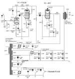
arnoldc said:hi gabe, i entered your op point into tube cad and this is what i got
Hey ArnoldC,
I can barely read that picture. What is it trying to say?
Gabe
hi frank,
that schematic is the same as the one posted by burnedfingers earlier. ironically, my chosen parts are almost the same as that one.
hi gabevee,
sorry about the small picture. attached, please find a better one. incidentally, i already plugged in into my amp and though it sounded better, i still got distortion in the output. so i was thinking i have a wrong operating point for the 807. a friend recommended that i wire the 807 in triode first, which i avoided because i wanted more power.
Attachments
IMHO the parallel 12AU7 isn't the best way to drive the 807... maybe a cathode follower or a totem pole. In my 807SE I used a PCL82 for driving the 807 into the positive grid region (A2) without big trouble.
ciao
Filippo
www.audiofanatic.it
ciao
Filippo
www.audiofanatic.it
Attachments
Hi,
Note also that Filippo used a separate screen supply which is how it is best done.
This is a snippet from a STC datasheet:
Cheers,
EDIT:The line at the bottom should read:
In cases where.......a potentiometer....and not by means of a series resistor.
Note also that Filippo used a separate screen supply which is how it is best done.
This is a snippet from a STC datasheet:
Cheers,
EDIT:The line at the bottom should read:
In cases where.......a potentiometer....and not by means of a series resistor.
Attachments
arnoldc said:sorry about the small picture. attached, please find a better one. incidentally, i already plugged in into my amp and though it sounded better, i still got distortion in the output. so i was thinking i have a wrong operating point for the 807. a friend recommended that i wire the 807 in triode first, which i avoided because i wanted more power. [/B]
Thanks!
BTW, Someone else posted that you need to put a bypass on the grid 2 circuit. What happens is that without the bypass capacitor, the grid 2 sees a fluctuation like that at the plate. In other words, it acts like a negative feedback grossly reducing your output, because it interacts with the input (grid 1), since grid 2 can also be an input grid, hence the distortion. I also made the same error when playing with my 6L6 SE amp. I bypassed the grid 2 and boy what sound! If that doesn't help, then dare I say the output transformer may be bad.
But, glad my suggestion helped make it sound better!
Gabe
Gabe
The unit I had used a 100 ohm resistor from grid 2 to the plate for triode mode. Should this have been bypassed or am I misunderstanding you?
The unit I had didn't have the cathode resistor bypassed either. Since I only could get .6watt out of it do you have any idea how much would have been gained by bypassing it too?
J
burnedfingers said:Gabe
The unit I had used a 100 ohm resistor from grid 2 to the plate for triode mode. Should this have been bypassed or am I misunderstanding you?
The unit I had didn't have the cathode resistor bypassed either. Since I only could get .6watt out of it do you have any idea how much would have been gained by bypassing it too?
J
Hi Burnedfingers,
When I put the bypass, power and subsequently volume went up to 6 watts... from 1.5 watts. I never had any luck using my 6L6's in triode mode. Not much output for any real comparison. Well, compared to a real triode like the 45 or 300B, anyway
For a triode connected tetrode/pentode, you do not bypass the 100 ohm resistor. One wants to have the screen grid to pretty much add to the plate with regards current flow. Bypassing will merely make it a tetrode with a very high voltage on the screen grid.
Gabe
hey there........there's some interesting fodder in SOUND PRACTICES magazine, fall 1992 quote <single 807 amplifier>; A cure for triode fever; by Gordon Rankin, Wavelength Audio. I think it's triode electronics website. I cannot give direct links as my system goes crazy.
There seems to be alot of info, but in all cases when we call the 807 a pentode, the g2 needs a stabilised source. The rest of the posters say same psalm....
rich
There seems to be alot of info, but in all cases when we call the 807 a pentode, the g2 needs a stabilised source. The rest of the posters say same psalm....
rich
This is a snippet from a STC datasheet
Please note that into the 6K load, nearly all of that lovely 12% harmonic distortion is 3rd order. The lower impedence load of 2.5K gives mostly 2nd harmonics. No offense to anyone here, but I can't imagine a single ended multi-grid tube amp ever sounding any good at all, unless it used an ultra-linear output transformer. Which leads to my next suggestion: The Lundahl website features a link to an EL-34 UL SE amp that looks well thought out and may well give you the ten good sounding watts you are after for a reasonable price.
John
The 807 should give 10 watts (60mA anode I) output in true tetrode mode with 450V B+ o/p tranny and stabilised 250V on g2 with 6Kohms o/p tranny....I've done such an animal!
Looking at the 807 charts, g1 is then lim to approx 20V onset clipping.....that leaves nearest 390 ohms for cathode resistor........ Someone else must have cobbled and got the same ????
rich
Looking at the 807 charts, g1 is then lim to approx 20V onset clipping.....that leaves nearest 390 ohms for cathode resistor........ Someone else must have cobbled and got the same ????
rich
Hi,
Yep...
The problems with the original circuit are manyfold in that the anode resistor for the 12AU7 are too low in value, the cathose resistor for the 807 seems off too and the screengrid is swinging along with the plate....Add to that that the 807 likes a higher B+ and you get the picture: distortion.
Cheers,
Someone else must have cobbled and got the same ????
Yep...
The problems with the original circuit are manyfold in that the anode resistor for the 12AU7 are too low in value, the cathose resistor for the 807 seems off too and the screengrid is swinging along with the plate....Add to that that the 807 likes a higher B+ and you get the picture: distortion.
Cheers,
Hi Rich,
If it's not on the website then, no, I don't.
Having seen other designs by him I take it distortion figures are acceptable.
Cheers,
Frank......for matter of curiosity, have you got the spec for that Aleksandar kitic RH807 amp ?
If it's not on the website then, no, I don't.
Having seen other designs by him I take it distortion figures are acceptable.
Cheers,
- Status
- This old topic is closed. If you want to reopen this topic, contact a moderator using the "Report Post" button.
- Home
- Amplifiers
- Tubes / Valves
- Distortion in 807 amplifier - please advise