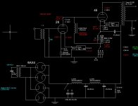
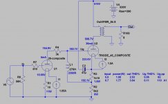
I just finished building a prototype of DC coupled SE amp, configured to use either #26 or #10 as a driver and #45 or VT52 as power tubes; it was quite tricky to get all the values right but it now works well in all 3 combinations (10-45, 26-45 and 10-VT52).
Here is the schematics, although few of the values are a bit tweaked on the prototype to get the right operating condition. I got #26 running at 180V/6mA/-13V bias and #45 at 270V/35mA/-53V bias (this are actual measured voltages).
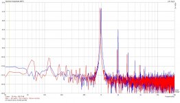
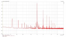
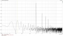
Amp already sounds very good to me, probably better then my 5687 IT coupled 211 Amp, but I was surprised a bit with pretty high THD I measured using Arta, see graphs below.
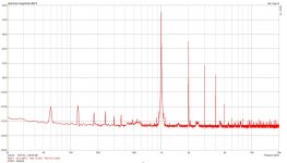
I included a comparison graph to my 211 amp (this one is done at 0.5W) which measures just 0.06%THD at 0.5W or around 0.1% at 1W while the new amp, regardless of tube combination used measures around 3% at 1W.
I was wondering if this is normal for #45 tube SE amp with no negative feedback or is there something I am missing?
Thanks for any suggestions!
Here is the schematics, although few of the values are a bit tweaked on the prototype to get the right operating condition. I got #26 running at 180V/6mA/-13V bias and #45 at 270V/35mA/-53V bias (this are actual measured voltages).
Amp already sounds very good to me, probably better then my 5687 IT coupled 211 Amp, but I was surprised a bit with pretty high THD I measured using Arta, see graphs below.
I included a comparison graph to my 211 amp (this one is done at 0.5W) which measures just 0.06%THD at 0.5W or around 0.1% at 1W while the new amp, regardless of tube combination used measures around 3% at 1W.
I was wondering if this is normal for #45 tube SE amp with no negative feedback or is there something I am missing?
Thanks for any suggestions!
Attachments
-
 26-45 schematics.jpg98.8 KB · Views: 657
 -
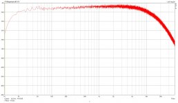 Frequency response.jpg120.3 KB · Views: 128
 -
 211 amp compared.jpg170.4 KB · Views: 132
 -
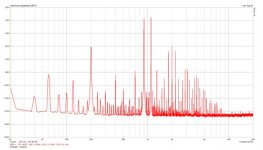 26-45, 990-1.1Khz at 1W.jpg51.3 KB · Views: 545
 -
 26-45, 1Khz at 1W.jpg45.8 KB · Views: 552
 -
 10-45, 990-1.1Khz at 1W.jpg141.1 KB · Views: 575
 -
 10-45, 1Khz at 1W.jpg118.6 KB · Views: 633
I don't know what would be 'normal' (even small changes can vary results a lot), but it's not unusual in my opinion.
You've got excellent tubes and ok topology. Now it's time to start experimenting and improving it.
My first pick to improve would be the PSU. Lower the PSU output impedance; regulate it.
Second would be to improve the input stage plate load.
Third would be to improve the output stage plate load, and change the direct coupling to source follower coupling. This way you retain (and in fact improve) the 45 grid drive conditions, and significantly improve the output stage linearity.
At that point you'll be looking at several tens dB less harmonics over the spectrum. And improved transient response.
I like the basic topology, but suspect you are running things just a bit too much on the edge.. I'd aim for about 150V on the plate of the 26 at 6mA, and something around 250V across the 45 at about 35mA to 40mA..
When I was working on my original 45 amplifier design almost 2 decades ago I found what I thought was a sweet spot in distortion spectra (and sound quality) at 250V and 38 - 40mA. Higher voltages at the same or lower currents measured worse and sounded worse too.
As a point of reference my first design cranked out a whopping 4% thd at its rated power of 1.6W. It's the only amp I designed and built in that time frame that I still own, and is in regular use with a friend at this time. Despite the obviously terrible distortion performance there is something fairly beguiling about it overall. (Note the thd is almost all 2nd with a smattering of third which may be why it is well liked.. lol) It's always been used with high efficiency speakers and in those scenarios thd of 0.4% at a couple of hundred mW is typical.
Hi euro21, I got a "switchable" PS for Rod's regulator, so when using 10/VT62 as a first stage I got 30V feeding Rod's regulator, 24.5V out of it, 7.5V drop on the tube filament and remaining 17V bias makes VT62 run at 275V/18mA, so it all works pretty well.
I did find quite some difference between current in the filaments between different #26 tubes as well as different VT62's, so had to adjust the filament bias resistor between 12.5, 13 or 13.5 ohm to get desired bias, depending on the actual tube used.
I did find quite some difference between current in the filaments between different #26 tubes as well as different VT62's, so had to adjust the filament bias resistor between 12.5, 13 or 13.5 ohm to get desired bias, depending on the actual tube used.
Thanks for the feedback, I did also have a look at Gorge's (Tubelab) Simple 45 measurements and it seems that I might be "in a ballpark" ") .
.
I really wanted to keep this amplifier simple, so that is why I decided to go with DC.
I will definitely try running #26 and #45 at lower voltages, as Kevin suggests; is it really OK to run #46 at 250V/38-40mA; I thought #45 should never exceed 26mA?
As for improving PS; what would be good suggestion on topology to lower output impedance/regulate PS?
.I really wanted to keep this amplifier simple, so that is why I decided to go with DC.
I will definitely try running #26 and #45 at lower voltages, as Kevin suggests; is it really OK to run #46 at 250V/38-40mA; I thought #45 should never exceed 26mA?
As for improving PS; what would be good suggestion on topology to lower output impedance/regulate PS?
Earlier specs on the 45 showed max plate voltage of 275. Later spec sheet did show an increase to 300V, but the max current remains at 36ma. My preference is 300V plate at 34ma of current which is just a tad over 10 watts dissipation. Pushing current higher than spec will decrease service life of a 45. Also note that the later spec is really for later ST glass versions which are better built.
Don't see any real problem with your output stage. You have closed the AC loop with a cap from the 45 cathode to the OPT B+ input. Your driver stage does not have any closed AC loop and should be re-examined. Bias points are on the upper edge and likely to be non-linear as you increase voltage drive, which needs to be pretty large due to the low mu of the 26.
Have you scoped the stages to get a view of how linear the waveform is? You might find that your input source is getting loaded from the 1:4 xfrmr and/or the grid of the 26 is being driven positive as the signal increases. I have two different 45 designs which are both fairly low on THD, around 0.4% or less at 1-watt output. I use an older HP 334a distortion analyzer and other older gear for measurements.
Your basic topology is similar to the old Robin & Lipman design, which is basically the Fi SE design. It does however have the AC loop closed on the driver stage via a decoupling cap to ground.
Regards, KM
rrrs your 211 amp is more powerful and it looks like is getting some substantial 2nd harmonic cancellation from the actual combination of driver stage/operative conditions.
You should also check how "new" are your tubes and the effective power loss of the output transformer (which is low if that is the Tango in the schematics but still subtracting a bit from your nominal 1W). For the 211 amp this is not a great deal being still pretty far away from max Pout. If your 26's and 45's are well used there is no issue and you might try do do the same trick as the 211 amp by canceling out some 2nd harmonic. If you load the 26 for max linearity you are not going to get it.
You should also check how "new" are your tubes and the effective power loss of the output transformer (which is low if that is the Tango in the schematics but still subtracting a bit from your nominal 1W). For the 211 amp this is not a great deal being still pretty far away from max Pout. If your 26's and 45's are well used there is no issue and you might try do do the same trick as the 211 amp by canceling out some 2nd harmonic. If you load the 26 for max linearity you are not going to get it.
I will definitely try running #26 and #45 at lower voltages
IMHO 530V too much, primarily for #45 (10W limit). Decrease it (increase PSU serial resistance, or regulate your PSU), until #45 anode voltage about 510V DC.
See my attachment.
#45 limit (275V, 36mA at -56V) defines (given anode voltage) R2, R3 (and #26 anode current through anode choke DCR), but in this case voltage is too high for #26. Use R4 serial resistor to decrease #26 anode voltage.
Attachments
For the driver stage, I thought a large 270H choke on the plate would act as a CC source and would nor require decoupling cap; anyway, will try adding a capacitor between "bottom" of the plate choke and #26 cathode and measure to see if anything changes.
I will also carefully check all PP voltages trough the amp and look for any visible distortion on sine wave just to make sure I am not driving any of the tubes near positive grid, but I believe this should not be the case. At 1W output I got approximately 8Vpp at OPT secondary, 200Vpp at #45 plate, 60Vpp on #26 plate, 7Vpp at #26 grid (input transformer secondary) and 1.75 Vpp at input transformer primary. Since my bias on #26 is at -13V and #45 at -50V I should have plenty of headroom before running close to positive grid?
Also on my 211 amp distortion (especially 2nd harmonic) changes quite a bit depending on actual 5687/211 tubes combination used, so sometimes this 2nd order cancelation happens and sometimes not as much; here is the plot I got measured at 5.6W, still at just 0.67% THD (my 211 amp is a very simple 2 stage, IT coupled, fixed negative bias used on both stages with cathode grounded).
As for the #26/45 tubes, thy appear to be new or at least very lightly used.
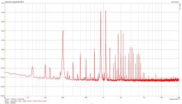
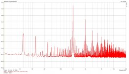
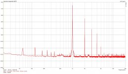
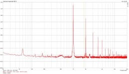
What I find particularly interesting is that in all 3 tube configurations (#25/#45, #10/#45 and #10/VT52) I am getting a very similar THD result, around 3%-3.5% at 1W; this is why I am suspecting there might be a problem with actual topology?
Here are spectrum comparisons of all 3 combinations, all at 1W.
What is interesting to see how much higher the 60Hz and 120Hz level is with #26 compared to #10 used in the first stage...and also additional HF noise present on RCA#26; I do not get this HF noise with Hytron#26, but do get same 60-120Hz noise.
I will also carefully check all PP voltages trough the amp and look for any visible distortion on sine wave just to make sure I am not driving any of the tubes near positive grid, but I believe this should not be the case. At 1W output I got approximately 8Vpp at OPT secondary, 200Vpp at #45 plate, 60Vpp on #26 plate, 7Vpp at #26 grid (input transformer secondary) and 1.75 Vpp at input transformer primary. Since my bias on #26 is at -13V and #45 at -50V I should have plenty of headroom before running close to positive grid?
Also on my 211 amp distortion (especially 2nd harmonic) changes quite a bit depending on actual 5687/211 tubes combination used, so sometimes this 2nd order cancelation happens and sometimes not as much; here is the plot I got measured at 5.6W, still at just 0.67% THD (my 211 amp is a very simple 2 stage, IT coupled, fixed negative bias used on both stages with cathode grounded).
As for the #26/45 tubes, thy appear to be new or at least very lightly used.
What I find particularly interesting is that in all 3 tube configurations (#25/#45, #10/#45 and #10/VT52) I am getting a very similar THD result, around 3%-3.5% at 1W; this is why I am suspecting there might be a problem with actual topology?
Here are spectrum comparisons of all 3 combinations, all at 1W.
What is interesting to see how much higher the 60Hz and 120Hz level is with #26 compared to #10 used in the first stage...and also additional HF noise present on RCA#26; I do not get this HF noise with Hytron#26, but do get same 60-120Hz noise.
Attachments
euro21, thanks for running a simulation for me, it is interesting to see that you get 2.5%THD at 1W, so not really that far from what I am measuring.
I will definitely adjust my operating points today and measure again; will target to get #26 at 150-160Von plate, 5-6mA current and #45 at 250V-260V, 34-36mA current.
I got a really nice power transformer from Thomas Mayer that features multiple secondary taps as well as primary +/-5% adjustment, so will be very easy to tweak voltages without any additional voltage drop resistors.
Will try to get 480V B+, 475V on #45 plate, 215V on cathode, 165V on #45 grid/#26 plate, 10-12V on #26 cathode (biased to get about 5.5mA current)
Yes, thanks, will try this later today....
As for the OPT I expect it should be a very good one based on feedback on the forum; it is Tango XE-20S I got long time ago with #45 project in mind...
Plate choke is Lundahl 270H/15mA, so should also be good.
I will try what happens adding a capacitor between #26 cathode and "bottom" of the choke to close the AC circuit more directly.
KMayer, would you mind sharing topology you used on #45 amplifier to get less then 1% distortion at 1W?
I have about two dozens of #26 tubes. Some of them very sensitive to (radiated) 50Hz, others are "silent". None of 10/801s or 841s are so sensible.What is interesting to see how much higher the 60Hz and 120Hz level is with #26 compared to #10 used in the first stage...and also additional HF noise present on RCA#26; I do not get this HF noise with Hytron#26, but do get same 60-120Hz noise.
I found what I thought was a sweet spot in distortion spectra (and sound quality) at 250V and 38 - 40mA. Higher voltages at the same or lower currents measured worse and sounded worse too.
Fully agree here. I find you can go a bit higher if you use a flatter load line. Of course then you need different iron... nice iron you have in this btw.
Last edited:
What I find particularly interesting is that in all 3 tube configurations (#25/#45, #10/#45 and #10/VT52) I am getting a very similar THD result, around 3%-3.5% at 1W; this is why I am suspecting there might be a problem with actual topology?
Try taking the entire power supply off board, or if that is too much trouble, put the OPT somewhere else... maybe on a nice soft rubber mat, but off the chassis.
You might be surprised.
As I said (in other words) 3% @ 1W is not the best you can get but is not horrible. You are getting close to the max Pout. What do you get at the max rated Pout (including the transformer loss)?What I find particularly interesting is that in all 3 tube configurations (#25/#45, #10/#45 and #10/VT52) I am getting a very similar THD result, around 3%-3.5% at 1W; this is why I am suspecting there might be a problem with actual topology?
Here are spectrum comparisons of all 3 combinations, all at 1W.
Once I did test all my 45 stock, nearly 30 tubes, to make some sort of selection. I run them at 270V/35-36mA. I had some well used but still good behaving like yours and others really new on the opposite side that were way better (I still have all of these). Being old tubes in different conditions you can have some substantial variance. I actually have one quad of Raytheons among the new ones that is more akin to VT-52 than 45 despite looking identical to all other 45's. In particular these have some 10%+ gm at any point of the plate curves I could reach safely and slightly more gain. I get more power out of these for any given THD.
Anyway the main difference I got between the "two lots" was that the new ones had less higher order HD and could get 1W within 1% THD without useful 2nd harmonic cancellation. I did the test using a front-end I built for a 300B amp for a friend of mine (i.e. 6SF5GT input stage RC coupled to a triode 46 transformer-coupled to the output tube using a Tango NC-20). The 45's were run with cathode grounded and fixed bias.
What is interesting to see how much higher the 60Hz and 120Hz level is with #26 compared to #10 used in the first stage...and also additional HF noise present on RCA#26; I do not get this HF noise with Hytron#26, but do get same 60-120Hz noise.
Same as above. What is the condition of your 26's? Some 26's are known to be prone to sing....some selection is needed. Of course the VT-62 is more linear when you want substantial drive like that.
Last edited:
I am still getting my 26/45 reconfigured to adjust operating points for lower voltage, as previously discussed; will report my findings.
At the same time could someone recommend a good operating point for #10 tube when used as a drier; I got them at the moment running at 280V/18mA/-16Vbias; any need/suggestion to change from here?
As well, I found that if I connect XE-20S as suggested (P to plate, B to B+ on primary and common pin #1 to ground/speaker negative, pin #12 for 5K into 8ohm load to speaker positive) it inverts the signal polarity; did someone else notice the same? Should I simply switch the secondary connections and use pin #1 as speaker positive, pin #12 connect to ground/speaker negative?
One more question on type of wire-wound resistors used throughout the amp; it is my understanding that there is absolutely ne need to use non-inductive resistors, except possibly on the driver tube cathode/filament bias. For all the other ones some inductance would change nothing (or possibly be a slight benefit )!? Could someone please confirm this is correct?
At the same time could someone recommend a good operating point for #10 tube when used as a drier; I got them at the moment running at 280V/18mA/-16Vbias; any need/suggestion to change from here?
As well, I found that if I connect XE-20S as suggested (P to plate, B to B+ on primary and common pin #1 to ground/speaker negative, pin #12 for 5K into 8ohm load to speaker positive) it inverts the signal polarity; did someone else notice the same? Should I simply switch the secondary connections and use pin #1 as speaker positive, pin #12 connect to ground/speaker negative?
One more question on type of wire-wound resistors used throughout the amp; it is my understanding that there is absolutely ne need to use non-inductive resistors, except possibly on the driver tube cathode/filament bias. For all the other ones some inductance would change nothing (or possibly be a slight benefit
)!? Could someone please confirm this is correct?- Status
- This old topic is closed. If you want to reopen this topic, contact a moderator using the "Report Post" button.
- Home
- Amplifiers
- Tubes / Valves
- Distortion expected in SE DC coupled 26/45 amp