For those that are interested in common-mode distortion in JFET-input op amps, and why it is dependent on source impedance for some op amps, I've written an article on this topic: http://www.ti.com/lit/an/slyt595/slyt595.pdf
Full disclosure: I am an applications engineer for TI Precision Analog in Tucson AZ. The article shows measurements on TI op amps, but the principles are applicable to JFET input op amps from most manufacturers.
Enjoy!
I'd be interested to see measurements of this part with the same conditions as in my opamp measurement series (linked in a previous post), i.e. voltage follower, 100k source R, +20 dBu, THD+N from 10 Hz to 200 kHz, no filter. Could you do this?
Note that substrate diodes aren't the only source of distortion. Gate-/base-drain capacitance contributes too, as do protection diodes (although these are usually small-geometry parts). There are even more subtle distortion mechanisms as a result from second stage effects which modulate the drain/collector voltage of the input transistors in a nonlinear fashion.
Samuel
Hi Samuel,
Great point about the ESD protection diodes and the Gate-to-source and Gate-to-drain capacitances of the input devices. While taking data for this article I compared op amps which bootstrapped the input devices to those that don't (I dug into the internal schematics to be sure) and found that the shift in the common-mode capacitance with common-mode voltage was similar for both types. This led me to the conclusion that the gate-to-substrate capacitance is the dominant contributor to this effect.
One aspect to consider on the ESD protection structures is that they may not always be as small as you think. In general, the delicate gate oxide layer of CMOS-input op amps requires more robust ESD protection and therefore larger devices. In my testing CMOS-input op amps had very flat CCM vs VCM but some deviation was apparent at more negative voltages. Overall their results were very good, and I think CMOS-input op amps probably are under-appreciated for many audio applications.
Hopefully I can do the testing you've asked for a bit later in the week. I went through your testing document (very impressive by the way, really excellent work) and I may also test the OPA827 again. Depending on the date of your test results, some improvements may have been made to that part.
older CMOS were avoided in audio for 1/f and even popcorn noise
are recent offerings are safe to use in audio without noise screening?
it would be nice to see from official datasheet info if the OPA827 is a real upgrade/replacement for the OPA627 in the input common mode linearity
are recent offerings are safe to use in audio without noise screening?
it would be nice to see from official datasheet info if the OPA827 is a real upgrade/replacement for the OPA627 in the input common mode linearity
Last edited:
older CMOS were avoided in audio for 1/f and even popcorn noise
are recent offerings are safe to use in audio without noise screening?
it would be nice to see from official datasheet info if the OPA827 is a real upgrade/replacement for the OPA627 in the input common mode linearity
Popcorn noise is typically more prevalent on bipolar processes as opposed to CMOS. But I won't be one of those engineers who claim that CMOS processes are popcorn free (otherwise CMOS image sensors would never exhibit "blinker" pixels). 1/f noise is still a very valid concern but a lot of work has gone into improving this in CMOS technology. As an example I refer you to the noise spectral density curve in the OPA172 datasheet. It's not at bipolar levels yet, but it is much improved over older parts with 100kHz noise corners.
In my opinion, whether or not noise screening is necessary depends on the application and how crucial the 1/f noise is to the total RMS noise. There can be much greater variability in the 1/f than in broadband because broadband is directly related to the gm of the input devices. So variations in broadband noise would also be associated with variations in other parameters and likely would be screened out in production. In many circuits broadband noise totally dominates the RMS noise voltage, and in those circuits noise screening is unnecessary. Others are very sensitive to 1/f noise (phono pre-amps come to mind due to the large amount of gain at low frequencies in the RIAA curve). So, it really depends on how the part is being used.
For those that are interested in common-mode distortion in JFET-input op amps, and why it is dependent on source impedance for some op amps, I've written an article on this topic: http://www.ti.com/lit/an/slyt595/slyt595.pdf
Full disclosure: I am an applications engineer for TI Precision Analog in Tucson AZ. The article shows measurements on TI op amps, but the principles are applicable to JFET input op amps from most manufacturers.
Enjoy!
Thanks a lot
")
I've certainly never seen plots of distortion vs. source impedance in any opamp datasheet. I believe the datasheet measurements for audio opamps are done with the 50 ohm output impedance of the Audio Precision analyser, as this gives the best results. Same as Douglas Self's measurements of power amp noise and distortion, but that is a different story.
Nor had I read about the effect in any textbook. The closest I saw was Williams' Law that says never to use opamps in the non-inverting mode in precision applications. I actually stumbled across the effect in the lab, when choosing an opamp to buffer the output level control in a low-distortion oscillator I was building. And I first came across "substrate bootstrapping" when poking around the innards of an old Farnell RC audio oscillator. I was trying to lower the distortion, but substituting an opamp with lower datasheet distortion figures made it worse. Then I spotted some weird circuitry around the negative supply rail and the penny dropped.
So I guess I am one of the "new generation" that jcx somewhat patronisingly refers to.
I've certainly never seen plots of distortion vs. source impedance in any opamp datasheet. I believe the datasheet measurements for audio opamps are done with the 50 ohm output impedance of the Audio Precision analyser, as this gives the best results. Same as Douglas Self's measurements of power amp noise and distortion, but that is a different story.
Nor had I read about the effect in any textbook. The closest I saw was Williams' Law that says never to use opamps in the non-inverting mode in precision applications. I actually stumbled across the effect in the lab, when choosing an opamp to buffer the output level control in a low-distortion oscillator I was building. And I first came across "substrate bootstrapping" when poking around the innards of an old Farnell RC audio oscillator. I was trying to lower the distortion, but substituting an opamp with lower datasheet distortion figures made it worse. Then I spotted some weird circuitry around the negative supply rail and the penny dropped.
So I guess I am one of the "new generation" that jcx somewhat patronisingly refers to.
Some op amps have THD+N vs source impedance graphs in the datasheet, ones that immediately come to mind are the OPA1612, 1602, 1652, and 1642 (although as previously stated the graph in the 1642 datasheet needs to be updated). These graphs are generally made by toggling the source impedance on the Audio Precision, but 600 ohms may not be high enough to reveal bad behavior. Shoot, I tested at 10k ohms and had a request for 100k!
In addition to distortion vs source impedance, I'm a big proponent of showing a plot of common-mode capacitance vs common-mode voltage. My applications engineer side has to wonder if the variation in common-mode capacitance couldn't actually be useful in some circuits. For example, to squeeze out an extra little bit of bandwidth from a transimpedance amplifier circuit you bias the input common mode near the upper power supply rail. Just a thought!
There's nothing wrong with being the new generation. In my opinion the "new generation" of engineers learning about analog consists of both younger engineers and older ones, but most were fed the same lie that "analog is dead" at some point in their career or education. Or that everything is going to be integrated...
Unfortunately, a lot of good engineering literature seems to disappear after some length of time, with those newly entering/re-entering the world of analog engineering having never been exposed to it. Even if some feel that my article is old news, its good to put it back out there for others to read.
On that note, we have an inside joke here in Tucson: any time one of your colleagues gets excited about a new idea that they have, immediately shout "Philbrick did it!" at them.
Great article. Can you say if the OPA2134 suffers in a similar way to the TL072?
Am I right in thinking most existing datasheets don't reveal this info?
Great work too on the active crossover reference design.
Yes, the OPA2134 and OPA2604 both show the same input characteristics as the TL072. The OPA2134 and OPA2604 datasheet have some recommendations in the applications sections to match the impedances at both inputs. But in my opinion its really too vague. Engineers need to see hard facts, numbers, results! So, it could use a much-needed injection of cause and effect in the description. This is one of the reasons why I wrote this article.
Thanks for your comment on the active crossover reference design! That was one of those projects where I couldn't believe I was getting paid to do it. Speaker building has been a hobby of mine since high school and when a coworker asked me if we could build him a set of studio monitors I thought it would be a great excuse to try active crossovers. When my boss got wind of the project he insisted that I write-up the project
One common use case would be buffering the wiper of a volume control. Douglas Self's power amp designs need this because he optimised them for 50 ohm source impedance. So now we need an integrated opamp to buffer the input of Self's discrete opamp, and another opamp to buffer that one...600 ohms may not be high enough to reveal bad behavior. Shoot, I tested at 10k ohms and had a request for 100k!
Another common use case is in guitar effects, where opamps are commonly used with high source impedances and a single 9V supply. The guitar weenies swear that the different makes and models of opamps sound different. In the light of these results, maybe there is some truth to that.
I've always been fascinated by analog, but some time in the 90s I made the mistake of getting involved with embedded programming and have been doing it ever since. I recently made a DSP clone of an old scientific instrument that was designed with analog techniques, and that a customer wanted a Mk2 version of. We were able to do everything in DSP cheaper than the old analog instrument, with greatly reduced factory test requirements.most were fed the same lie that "analog is dead" at some point in their career or education. Or that everything is going to be integrated...
Analog devices (and Analog Devices for that matter
) seem to be doing fine, but analog applications are getting a bit thin on the ground.Well, it's probably true!we have an inside joke here in Tucson: any time one of your colleagues gets excited about a new idea that they have, immediately shout "Philbrick did it!" at them.
The modern version of this is to Google the idea that you just thought of. Odds are that 8 people have already done it and put it on Kickstarter.
Last edited:
D.Self mentions it in ed6 of his Audio Power Amp design.I've certainly never seen plots of distortion vs. source impedance in any opamp datasheet. .................
Nor had I read about the effect in any textbook. .............
It was not in ed2.
D.Self has also mentioned it on this Forum. Can't recall the context, nor the Thread.
D.Self mentions it in ed6 of his Audio Power Amp design.
It was not in ed2.
D.Self has also mentioned it on this Forum. Can't recall the context, nor the Thread.
His book: Small Signal Audio Design also shows the effects in op amp circuits. "Active Crossover Design" may describe it as well because this is an important consideration in Sallen-Key filters (as Scott Wurcer mentioned earlier in this thread).
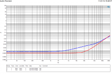
As Mr. Groner requested, I tested the OPA1641 with a source impedance of 100kOhm up to 200kHz. Unfortunately, my Audio Precision would only let me do a signal amplitude of +18dBu (6.153Vrms) to 200kHz as opposed to the +20dBu he used in his testing. As a bonus, I also measured the OPA827 under the same conditions. The two plots are attached, in both graphs the blue curve is for a source impedance of 100kOhms, the red curve is for a source impedance of 20 ohms.
Enjoy!
Enjoy!
Attachments
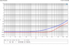
So, what exactly does this show Mr. Caldwell...that distortion rises as the source impedance goes down?
Is the OPA827 supposed to be comparable and or better than the OPA1641 in some way(s)?
For audio applications, why would one be concerned with what's going on at 200KHz?
Thanks...
Is the OPA827 supposed to be comparable and or better than the OPA1641 in some way(s)?
For audio applications, why would one be concerned with what's going on at 200KHz?
Thanks...
So, what exactly does this show Mr. Caldwell...that distortion rises as the source impedance goes down?
Is the OPA827 supposed to be comparable and or better than the OPA1641 in some way(s)?
For audio applications, why would one be concerned with what's going on at 200KHz?
Thanks...
The graphs show that distortion increases for higher source impedances (100k ohm source impedance has higher THD+N than the 20 ohm curve). This is not unexpected, as others pointed out in the thread, the gate-to-substrate capacitance is not the only non-linear capacitance in the op amp input, just the largest. However, the input stage may be designed to maintain a constant VDS across the input JFETs (cascoding), bootstrapping the gate-to-source and gate-to-drain capacitances and eliminating their effects on the input capacitance of the op amp. At higher frequencies, the cascode circuitry may not have sufficient bandwidth to keep up with the input signal, and the additional non-linear capacitances of the input JFETs begin to affect the distortion performance of the circuit.
Within the audio bandwidth I would say that the OPA1641 and OPA827 performance is comparable. I included the OPA827 results because Samuel Groner's testing of the OPA827 showed much higher distortion at high source impedance and I was curious if a process change had improved the performance.
Finally, why care about the performance above 20kHz? Non-linearity outside of the audio bandwidth can translate into weird behavior inside the audio bandwidth due to intermodulation effects.
It was my understanding that Stewart Hegeman (among others), design and recording engineer, did research into this and concluded that people canFinally, why care about the performance above 20kHz? Non-linearity outside of the audio bandwidth can translate into weird behavior inside the audio bandwidth due to intermodulation effects.
perceive and experience well beyond 20,000 cycles. He also was concerned
about listener fatigue.
He thought that performance below 20 cycles was very important as well as frequency response above 100,000 cycles. 20 Hz to lay the foundation of the music, 100 kHz offers cleaner transparent tone and instrument separation.
This from an article Golden Age of Stereo, Harman-Kardon Citation I and II by Charlie Kittleson, Vacuum Tube Valley, date and issue unknown.
My own experience with this is that it is probably a lot more important
than many people realize. And once we start hacking voice, music, sounds into rectangles then trying to put it back together again.
...and the beat goes on.
It was my understanding that Stewart Hegeman (among others), design and recording engineer, did research into this and concluded that people can
perceive and experience well beyond 20,000 cycles. He also was concerned
about listener fatigue.
He thought that performance below 20 cycles was very important as well as frequency response above 100,000 cycles. 20 Hz to lay the foundation of the music, 100 kHz offers cleaner transparent tone and instrument separation.
This from an article Golden Age of Stereo, Harman-Kardon Citation I and II by Charlie Kittleson, Vacuum Tube Valley, date and issue unknown.
My own experience with this is that it is probably a lot more important
than many people realize. And once we start hacking voice, music, sounds into rectangles then trying to put it back together again.
...and the beat goes on.
These are really great points.
I'm a bit confused. So the common mode distortion is not only affected by the source impedance, also by the input voltage swing? and the only way to really avoid it will be a inverting topology, is that correct?
What about behind the volume pot, I'm thinking of a configuration amplify signal first then 10k pot + buffer, either opa1642 or opa827, which one is better in this case?
What about behind the volume pot, I'm thinking of a configuration amplify signal first then 10k pot + buffer, either opa1642 or opa827, which one is better in this case?
- Home
- Source & Line
- Analog Line Level
- Distortion and Source Impedance in JFET Input Op Amps