Simulations II
Another circuit was created, where the Vds loss of the gain transistor has now been
compensated for.
Please take a look at the picture below:
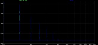
Blue trace is still the circuit with No feedback.
Green trace is the circuit still with 15 dB feedback, but now with Vds compensation, roughly
corresponding to the loss of Vds due to the insertion of degenerative resistor element in the
Source circuit.
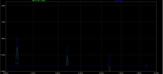
As can be see, there are no higher order harmonics present, and the feedback
factor is still 15 dB, roughly corresponding to approximately 15 dB of lower
amplitude on the 2nd, 3rd, 4th and so on.
This can be seen on the second, zoomed-in graph.
Another circuit was created, where the Vds loss of the gain transistor has now been
compensated for.
Please take a look at the picture below:
Blue trace is still the circuit with No feedback.
Green trace is the circuit still with 15 dB feedback, but now with Vds compensation, roughly
corresponding to the loss of Vds due to the insertion of degenerative resistor element in the
Source circuit.
As can be see, there are no higher order harmonics present, and the feedback
factor is still 15 dB, roughly corresponding to approximately 15 dB of lower
amplitude on the 2nd, 3rd, 4th and so on.
This can be seen on the second, zoomed-in graph.
Attachments
Simulation II - reflections on the results
The results of the above-mentioned simulations obviously contradict the claims made by
Pass Labs (and the late Mr Baxandall - RIP).
The higher order harmonics created in the circuit example featuriing 15 dB of
degenerative feedback seem to be the result of slight signal compression, due to
static and dynamic loss of Vds due to insertion of degenerative feedback element in
the output loop, inevitably causing substantial change in transistor operating point.
NOT because of feedback.
Feedback, when applied properly, will not lead to higher order distortion or complexity.
Remember that these are the results of simulations.
At this point, it would be very beneficial to verify this in real life.
Thank you all for your comments.
Last edited:
Simulation II - reflections on the results
The higher order harmonics created in the circuit example featuriing 15 dB of
degenerative feedback seem to be the result of slight signal compression, due to
static and dynamic loss of Vds due to insertion of degenerative feedback element in
the output loop, inevitably causing substantial change in transistor operating point.
NOT because of feedback.
Nothing new about that.
Use degeneration sparingly.
Nothing new about that.
------------------------------------------------------------------------------
Yes, however, this is contrary to what Pass Labs claims.
It is clearly stated in their paper:
" negative feedback can reduce the total quantity of distortion, but it adds new components on its own".
This simply appears not to be the case.
https://passlabs.com/sites/default/files/distortion_and_feedback.pdf
Last edited:
Use degeneration sparingly.
No.
Any type of feedback, weather "degenerative" or not, will lead to
higher linearity and lowered distortion.
But as with anything, it has to be applied correctly.
That is the whole point of the series of simulations and discussion here.
------------------------------------------------------------------------------
Yes, however, this is contrary to what Pass Labs claims.
It is clearly stated in their paper:
" negative feedback can reduce the total quantity of distortion, but it adds new components on its own".
This simply appears not to be the case.
https://passlabs.com/sites/default/files/distortion_and_feedback.pdf
He probably meant that if it requires adding multiple gain stages to achieve the required feedback figure then you will get increasingly higher order harmonics.
No.
Any type of feedback, weather "degenerative" or not, will lead to
higher linearity and lowered distortion.
But as with anything, it has to be applied correctly.
That is the whole point of the series of simulations and discussion here.
I've found adding degeneration has a far more negative effect than negative feedback.
Eg 20dB degeneration (zero feedback) vs 20dB negative feedback (zero degeneration)
I know the one I'll choose every time.
Simulations III - 20 kHz
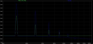
Here is the simulations of a 20 kHz signal, 1W into 8 ohms resistive load.
Zoomed at harmonics components.
- Blue is the no Feedback amp
- Green is the 15 db feedback circuit with Vds compensation.
The amplifier circuit featuring 15 dB degenerative feedback is more
linear even at 20 kHz.
Here is the simulations of a 20 kHz signal, 1W into 8 ohms resistive load.
Zoomed at harmonics components.
- Blue is the no Feedback amp
- Green is the 15 db feedback circuit with Vds compensation.
The amplifier circuit featuring 15 dB degenerative feedback is more
linear even at 20 kHz.
Attachments
Simulations IV
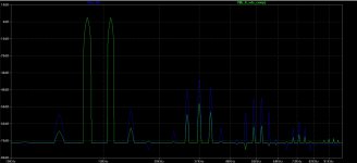
The high frequency IM test is more revealing than single tone test signals.
They better expose gain irregularities.
So here is the simulation of 1W into resistive 8 ohms of 17 kHz and 20 kHz signals:
As before:
- Blue trace is the non feedback circuit.
- Green trace is the circuit with 15 dB feedback circuit and Vds compensation.
The no feedback circuit has problems reproducing this mixture as evidently
depicted in the graph below.
The highly bent transfer function of the non-feedback circuit more readily
creates sidebands of the input signal, whereas the circuit with 15 dB feedback
is more linear.
Attachments
Simulations III - 20 kHz
Here is the simulations of a 20 kHz signal, 1W into 8 ohms resistive load.
Zoomed at harmonics components.
- Blue is the no Feedback amp
- Green is the 15 db feedback circuit with Vds compensation.
The amplifier circuit featuring 15 dB degenerative feedback is more
linear even at 20 kHz.
This is honestly not very helpful. It's just ranting without providing full circuit details and full test conditions.
Repeat test but this time 16V pk into 4 Ohms.for both circuits.
That's about all I have time for or I'll also be in need of a kidney transplant.
Last edited:
Are you in need of a kidney transplant.

What's a few PPM between friends?
What's a few PPM between friends?
It's the ppm that makes all the difference.
Hahaha
------------------------------------------------------------------------This is honestly not very helpful. It's just ranting without providing full circuit details and full test conditions.
Repeat test but this time 16V pk into 4 Ohms.for both circuits.
That's about all I have time for or I'll also be in need of a kidney transplant.
As mentioned previously, the simulation circuit is identical to that of the Pass Labs paper. That is:
SE MosFet IRFP240 pspice model.
2 Adc Bias.
11 Vds.
1W into 8 ohms resistive load.
Circuit 1: No degenerative fb.
Circuit 2: 15 dB degenerative fb.
Please see the previous posts.
These were all mentioned in my first posts.
Repeating the test for 16 V into 4 ohms does not provide comparative data to
information presented in the Pass Labs document.
Degeneration is negative feedback. Write it out 100 times.2 picoDumbs said:I've found adding degeneration has a far more negative effect than negative feedback.
Eg 20dB degeneration (zero feedback) vs 20dB negative feedback (zero degeneration)
- Home
- Amplifiers
- Pass Labs
- Distortion and Negative Feedback